Vehicular camera with aligned housing members and electrical connection between aligned housing members

a technology of aligned housing and camera body, which is applied in the field of rearview cameras, can solve the problems of imposing space restrictions on the camera, affecting the quality of the camera, and the relative severe space restrictions of the camera, so as to reduce the space occupied by the camera, eliminate potential circuit failure sources, and reduce the cost

Active Publication Date: 2016-01-12
MAGNA ELECTRONICS INC
View PDF46 Cites 111 Cited by
  • Summary
  • Abstract
  • Description
  • Claims
  • Application Information

AI Technical Summary

Benefits of technology

[0007]By directly mounting the front and rear electrical connectors, a jumper wire is not needed, thereby reducing cost and eliminating potential sources of circuit failures that are associated with the use of jumper wires. By aligning the front and rear housing members, the overall space occupied by the camera is smaller, which is advantageous particularly when the camera is to be used in tight spaces.

Problems solved by technology

In particular, for certain applications, such as for some applications wherein the camera is rearwardly facing and is mounted in a rear panel on a vehicle, there can be relatively severe space restrictions for the camera.
However, other vehicular camera applications also impose space restrictions on the camera.
Additionally, some cameras are relatively complex assemblies that are expensive, and can suffer from reliability problems due to the number of components and the number of individual electrical connections that are associated therewith.

Method used


Image

  • Vehicular camera with aligned housing members and electrical connection between aligned housing members
  • Vehicular camera with aligned housing members and electrical connection between aligned housing members
  • Vehicular camera with aligned housing members and electrical connection between aligned housing members

Examples


Embodiment Construction

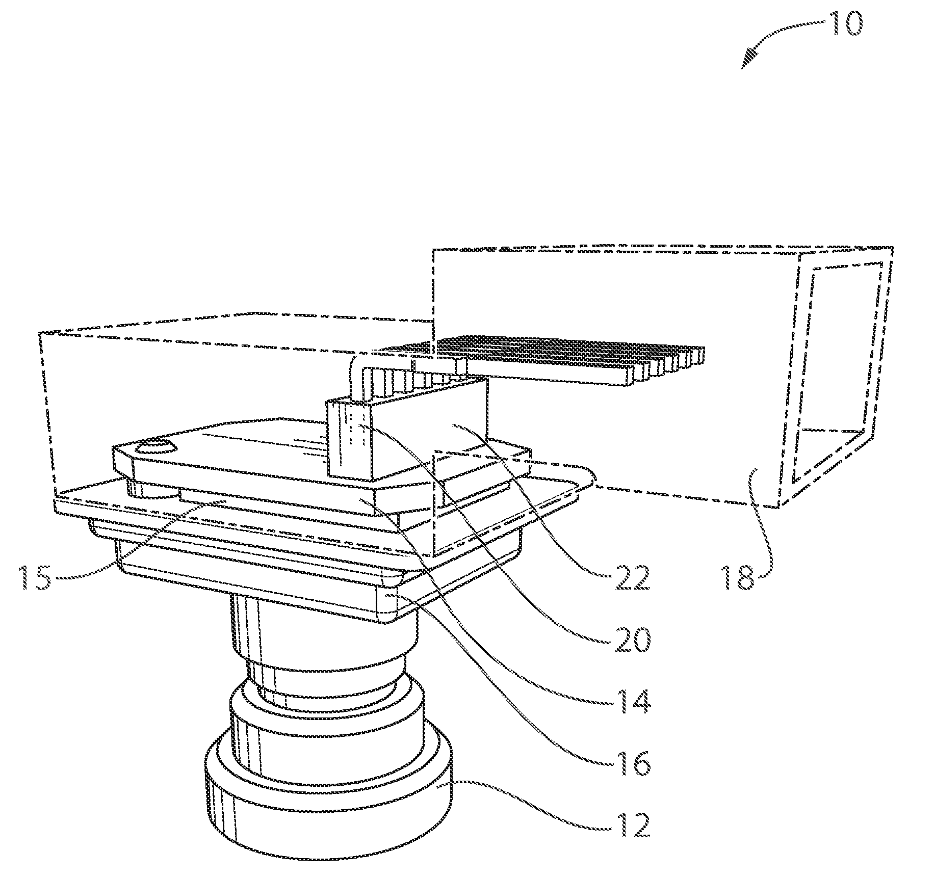
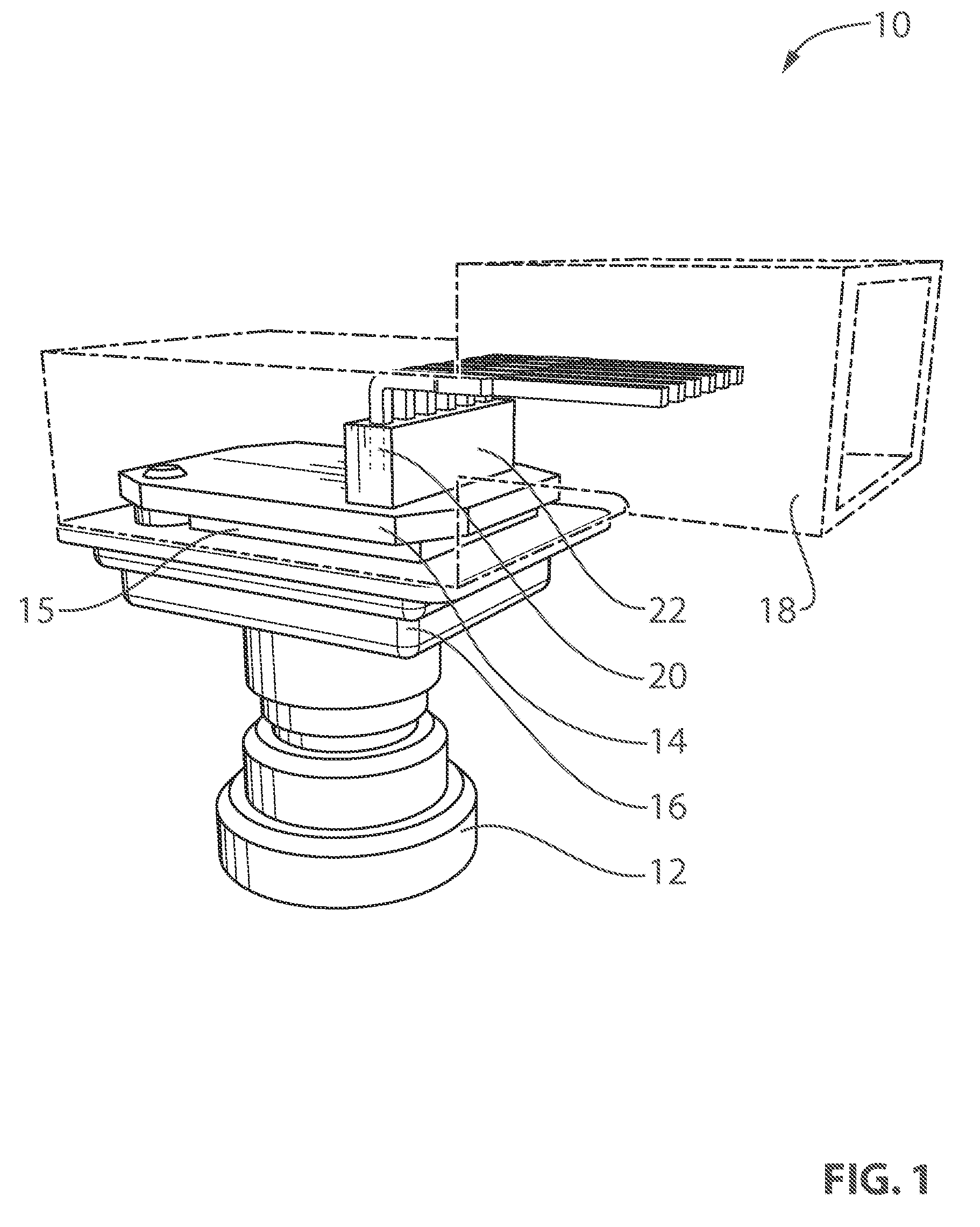
[0019]Reference is made to FIG. 1, which shows a camera 10 for use in a vehicle (not shown), and in particular for use as a rearview camera in a vehicle. The camera 10 includes an optical element or lens assembly or lens member 12, a circuit board 14, an imager 15, a front housing member 16 and a rear housing member 18 (shown in FIG. 1 as being transparent). The lens member 12 may be any suitable lens member known in the art, and is mounted to the front housing member 16. In some instances the lens member 12 may a separate element from the front housing member 16, or it may be integral with the front housing member 16.

[0020]Note that the terms ‘front’ and ‘rear’ as used in the present document refer to the front of the camera 10 (i.e., the portion of the camera where the lens member is located), and the rear of the camera 10 (i.e., the portion of the camera 10 opposite the front of the camera 10). When the camera 10 is used in a rearview application in a vehicle (such as when the ca...


PUM


Abstract

A camera for mounting on a vehicle includes a front housing member that holds a lens member, an imaging element and a circuit board with a set of front electrical connectors thereon, and a rear housing member that holds a set of rear electrical connectors that are directly mounted to the front electrical connectors. The rear housing member is aligned to the front housing member with respect to a first axis. The front and rear electrical connectors are able to accommodate misalignment along two axes which are generally orthogonal to each other and to the first axis. The front and rear electrical connectors may be directly connected so that a jumper wire is not needed. Also, by aligning the front and rear housing members, the overall space occupied by the camera may be reduced.

Description

CROSS REFERENCE TO RELATED APPLICATIONS[0001]The present application is a 371 national phase filing of PCT Application No. PCT / US2012 / 026073, filed Feb. 22. 2012, which claims the filing benefit of U.S. provisional applications, Ser. No. 61 / 593,962, filed Feb. 2, 2012, and Ser. No. 61 / 446,975, filed Feb. 25, 2011, which are hereby incorporated herein by reference in their entireties.FIELD OF THE INVENTION[0002]The present invention relates to cameras for use in vehicles, and more particularly to rearview cameras.BACKGROUND OF THE INVENTION[0003]A typical camera for mounting on a vehicle has a lens member, an imaging element, a circuit board and housing members that connect together. In particular, for certain applications, such as for some applications wherein the camera is rearwardly facing and is mounted in a rear panel on a vehicle, there can be relatively severe space restrictions for the camera. However, other vehicular camera applications also impose space restrictions on the ...

Claims


Application Information

Patent Timeline
Patent Type & Authority Patents(United States)
IPC IPC(8): H04N5/225H01R12/91B60Q9/00H01R13/11H01R12/71B60R11/04
CPCB60Q9/008H01R12/91B60R11/04H01R12/716H01R13/112H04N23/51
Inventor SESTI, MATTHEW C.BYRNE, STEVEN V.
Owner MAGNA ELECTRONICS INC
Why Eureka
Try Eureka