Scooter with rear swivel wheel

a rear swivel wheel and scooter technology, applied in the field of personal mobility vehicles, can solve the problems of ineffective and ineffective braking mechanisms of conventional scooters, and the user is also limited to steering the front wheel of conventional scooters, so as to increase the enjoyment of users

Active Publication Date: 2014-10-28
RAZOR USA
View PDF47 Cites 48 Cited by
  • Summary
  • Abstract
  • Description
  • Claims
  • Application Information

AI Technical Summary

Benefits of technology

[0007]An aspect of the present invention is the realization that allowing the user to perform a side to side movement or allowing the user to direct the riding board in a sideways arcuate path, is practicable with a two-wheeled scooter (e.g., a kick-scooter) and would increase the user's enjoyment and providing additional ability for advanced users to perform various stunts or tricks.
[0008]Conventional scooter braking mechanisms can be ineffective and would not function effectively with a pivoting or swiveling wheel. Also, using a conventional scooter, a user is only able to propel the scooter forward by pushing off the ground with one of the user's feet. A user is also limited to steering the front wheel of the conventional scooter, and continues moving forward in a generally limited direction and orientation. What is needed is an improved and new scooter and brake design that provides alternative range of movement to the user.
[0009]Preferred embodiments of the personal mobility vehicle are configured to allow a user to propel a caster-wheeled scooter by pushing off of the ground with one of the user's feet. A user is able to cause the scooter to travel in a generally linear forward direction by steering the front wheel with a handlebar assembly configured to change the direction of the front wheel. Preferred embodiments of the scooter also generally include at least one swivel caster wheel located on the rear of the scooter, allowing the user to cause the scooter to travel in a non-linear movement or ride the scooter using a side to side motion similar to the rear movement of a swivel caster board.
[0012]Another preferred embodiment is a scooter having at least one swivel caster wheel mounted on the rear of the scooter, and at least one swivel caster wheel mounted on the front of the scooter, with the front swivel caster wheel operably coupled to a steering mechanism available to the user. In this embodiment, the user is able to cause the scooter to travel in a generally linear forward direction by pushing off of the ground with one of the user's feet and directing the front wheel with the steering mechanism. The user is also able to propel the scooter forward using a side to side motion which causes the scooter to propel forward due to the front and rear swivel caster wheels being mounted at an angle relative to the user support platform.
[0013]In this embodiment, the front swivel caster wheel may have a centering mechanism biasing the caster wheel to a neutral steering position. A spring action device may be mounted between the caster wheel assembly and some fixed portion of the user support platform of the scooter to provide rotational resistance to the caster wheel. In another preferred embodiment, self-centering of the swivel caster assembly may be provided by a torsion spring arrangement, such as a helical torsion spring. In these embodiments, the self-centering spring provides resistance to pivoting or turning of the swivel caster wheel assembly fork about its turning axis allowing the caster wheel to be steered by the user. The self-centering spring mechanism may also provide rotational resistance and a biasing force on the swivel caster wheel to return the swivel caster wheel to its neutral steering position when the scooter is being propelled by side to side movement by the user to propel the scooter in a forward direction.

Problems solved by technology

Conventional scooter braking mechanisms can be ineffective and would not function effectively with a pivoting or swiveling wheel.
Also, using a conventional scooter, a user is only able to propel the scooter forward by pushing off the ground with one of the user's feet.
A user is also limited to steering the front wheel of the conventional scooter, and continues moving forward in a generally limited direction and orientation.

Method used


Image

  • Scooter with rear swivel wheel
  • Scooter with rear swivel wheel
  • Scooter with rear swivel wheel

Examples


Embodiment Construction

[0026]Reference will now be made in detail to the embodiments of the present technology. While numerous specific embodiments of the present technology will be described in conjunction with the alternative embodiments, it will be understood that they are not intended to limit the present technology to these embodiments. Instead, these described embodiments of the present technology are intended to cover alternatives, modifications and equivalents. Furthermore, in the following detailed numerous specific details are set forth in order to provide a thorough understanding of the present technology. However, it will be recognized by one of ordinary skill in the art that embodiments may be practiced without these specific details. In other instances, well known methods, procedures, components, compositions and mechanisms have not been described in detail as not to unnecessarily obscure aspects of embodiments of the present technology.

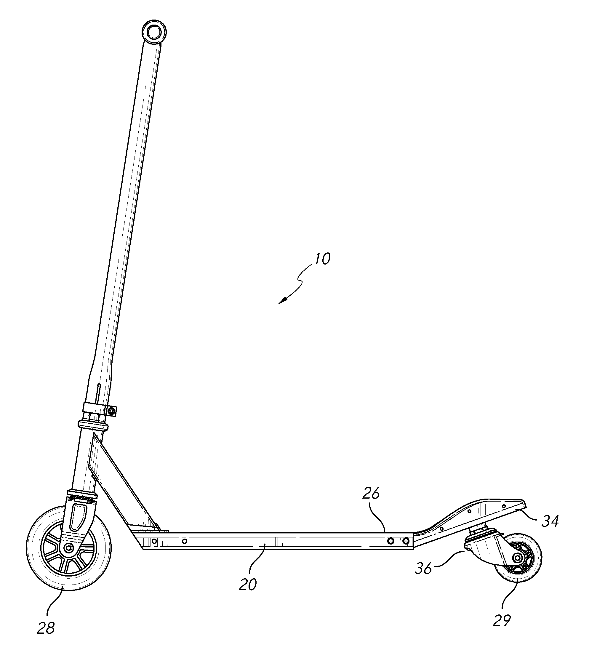
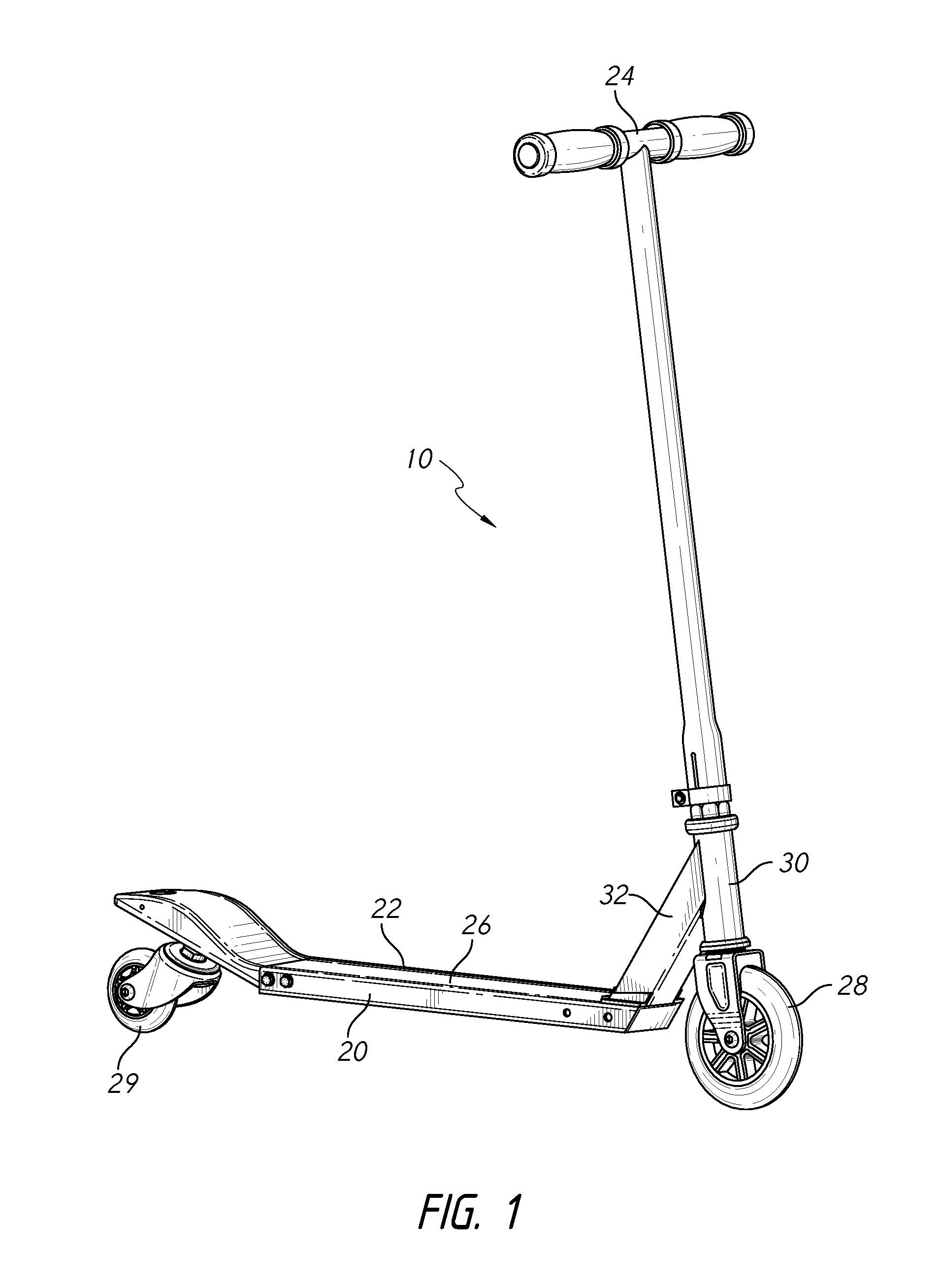
[0027]FIG. 1 shows a scooter 10 having certain features...


PUM


Abstract

A personal mobility vehicle or scooter includes a least one swivel caster wheel supported at the rear of the scooter. The scooter has a body that includes a deck and a handlebar assembly. The scooter includes at least one front wheel with the deck extending between the at least one front wheel and the at least one swivel wheel. The scooter can also include an angled rear portion supporting a rear swivel caster wheel such that the pivot axis of the swivel wheel is inclined with respect to the top surface of the deck. Embodiments of the scooter also include a swivel braking assembly configured to apply a braking force to the at least one swivel wheel.

Description

PRIORITY INFORMATION[0001]The present application claims benefit under 35 U.S.C. §119(e) to U.S. Provisional Patent Application No. 61 / 616,121, filed Mar. 27, 2012, entitled “SCOOTER WITH REAR SWIVEL CASTER WHEEL,” the entire contents of which is hereby expressly incorporated by reference.BACKGROUND OF THE DISCLOSURE[0002]1. Field of the Invention[0003]Embodiments of the invention relate generally to personal mobility vehicles and, more specifically, to a scooter having at least one swivel caster wheel located at the rear portion of the scooter.[0004]2. Description of the Related Art[0005]The use of personal mobility vehicles, such as scooters, has become a popular recreational activity as well as useful means of personal transportation. Scooters have become popular among many age groups and there are many different scooter variations and scooter designs. Scooter designs have become more compact and convenient, and many scooters have folding mechanisms allowing the user to easily st...

Claims


Application Information

Patent Timeline
Patent Type & Authority Patents(United States)
IPC IPC(8): B62K15/00B62K21/00B62K3/02B62B3/00
CPCB62B3/001B62K3/002B62K21/12B62L1/04B62L3/04
Inventor CHEN, ROBERT
Owner RAZOR USA
Why Eureka
Try Eureka