Light guiding sysetm, edge type backlight module and liquid display device

a technology of liquid crystal display and light guiding system, which is applied in the field of light guiding system, edge-type backlight module and liquid crystal display device, can solve the problems of increasing cost and manufacturing complexity, increasing environmental problems, and accumulating to a large amount, and achieving the reduction of dimension and weight of edge-type backlight module, reducing the width and length of light guiding bar 40, and reducing the optical path within the light guiding bar.

Active Publication Date: 2014-10-28
TCL CHINA STAR OPTOELECTRONICS TECH CO LTD
View PDF1 Cites 0 Cited by
  • Summary
  • Abstract
  • Description
  • Claims
  • Application Information

AI Technical Summary

Benefits of technology

[0026]In view of the above, by adopting two light guiding bars, the plurality of optical fibers may be divided into two groups. With such configuration, not only the width and the length of the light guiding bar 40 are decreased, but also the dimension and the weight of the edge-type backlight module are decreased. At the same time, the optical path within the light guiding bar is shortened. By configuring the shape and the arrangement of the dots on the light guiding bar, the lights from the light emitting ends uniformly radiate to the light guiding plate such that the optical performance of the edge-type backlight module is enhanced.

Problems solved by technology

As the power consumptions of the backlight source may be over eighty percents of the total amount of the power consumptions, it may be accumulated to a huge amount after a long period of time.
Currently, oil-fired, coal-fired, or nuclear electricity are major power generation methods, which may result in environmental problems such as greenhouse effect, nuclear pollution, and so on.
The main problem of the above backlight module structure resides in that the emitting angle of the light emitting ends 21 of the optical fibers 20 is small than 60 degrees.
However, the cost and the manufacturing complexity are increased with such solution.

Method used


Image

  • Light guiding sysetm, edge type backlight module and liquid display device
  • Light guiding sysetm, edge type backlight module and liquid display device
  • Light guiding sysetm, edge type backlight module and liquid display device

Examples


Embodiment Construction

[0033]Embodiments of the invention will now be described more fully hereinafter with reference to the accompanying drawings, in which embodiments of the invention are shown.

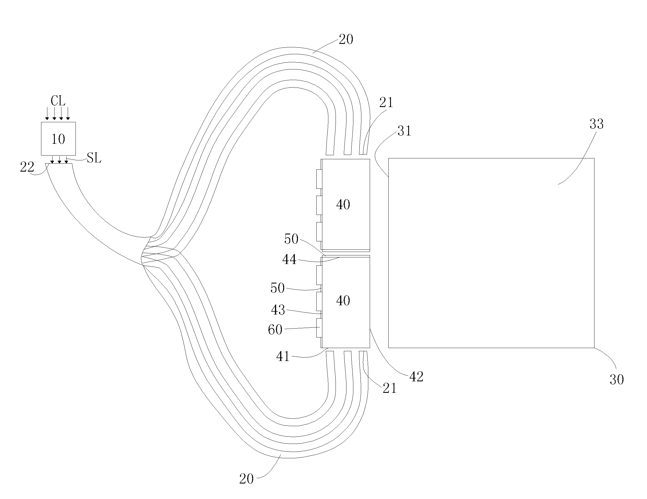
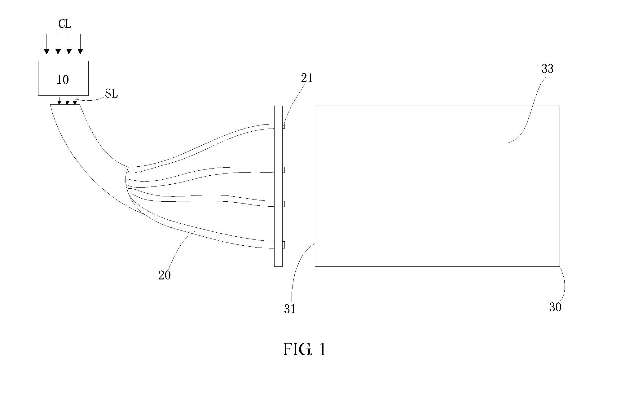
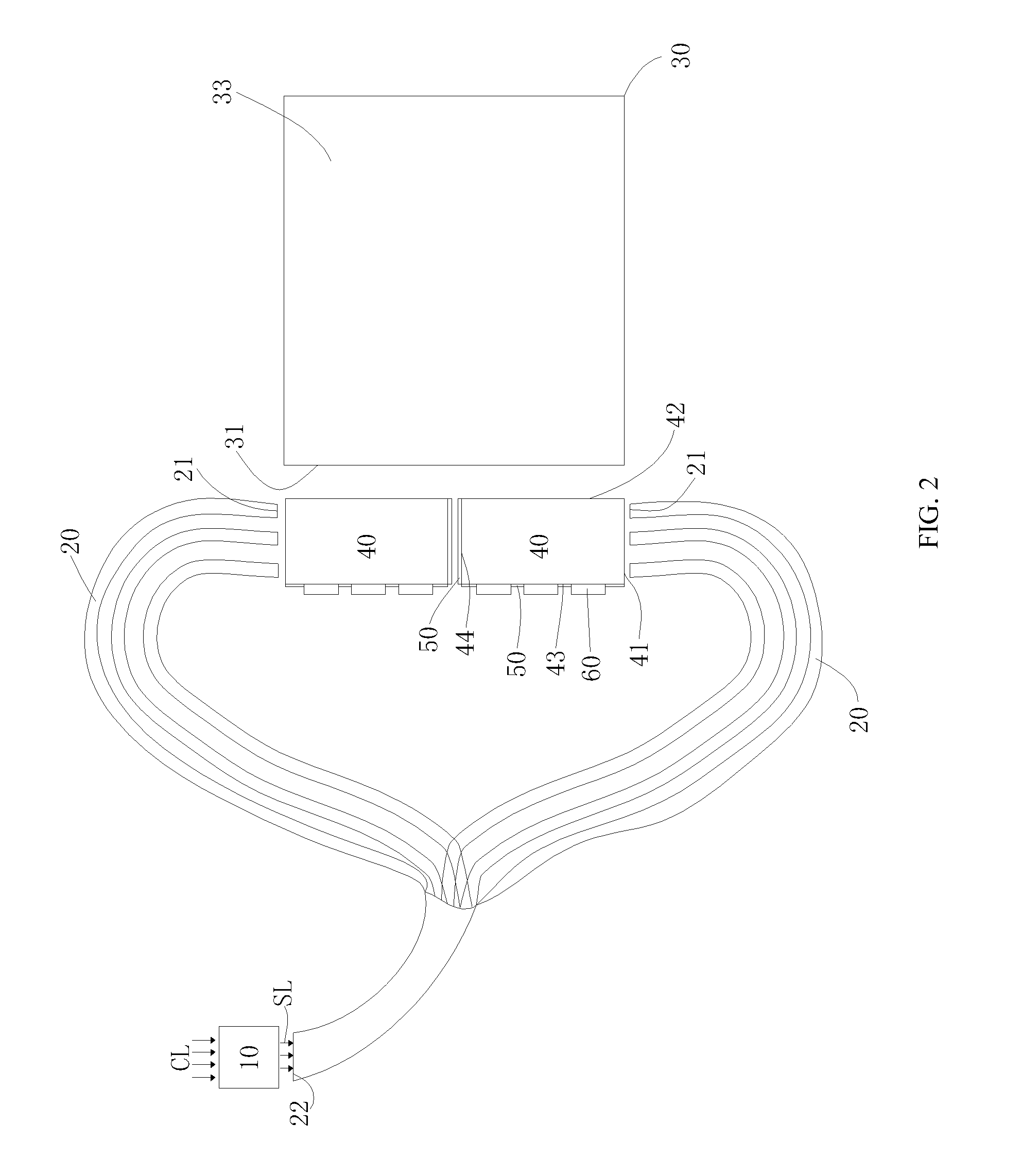
[0034]Referring to FIGS. 2 and 3, the light guiding system 1 includes an ambient light collection system 10, a plurality of optical fibers 20, and two light guiding bars 40. Specifically, the ambient light collection system 10 faces toward the ambient light CL and absorbs the ambient light CL, and then the ambient light CL are transformed to the absorbed light SL. It is to be noted that the ambient light CL may be lights from sun, lamps, or other lighting objects. The wavelength of the absorbed light SL is within the scope of visible light wavelength. That is, the absorbed light SL may be the backlight source of the backlight module. Each of the optical fibers 20 includes a light emitting end 21 and a light incident end 22. The light incident ends 22 of the optical fibers 20 are coupled together and are arranged ...


PUM

PropertyMeasurementUnit
emitting angleaaaaaaaaaa
electrical poweraaaaaaaaaa
power consumptionsaaaaaaaaaa

Abstract

A light guiding system, an edge type backlight module and a liquid crystal display are disclosed. The light guiding system includes an ambient light collection system facing toward ambient light to absorb the ambient light and to generate absorbed light, a plurality of light guiding devices, and at least a first and a second light guiding bar. Each of the light guiding devices includes a light emitting end and a light incident end. The light incident ends of the optical fibers are arranged close to the ambient light collection system, and the lights entered from the light incident ends are propagated toward the light emitting ends. Each of the light guiding bars includes a light emitting surface, a light incident surface connected to the light emitting surface, and a first lateral side opposite to the light incident surface.

Description

BACKGROUND OF THE INVENTION[0001]1. Field of the Invention[0002]Embodiments of the present disclosure relate to liquid crystal display technology, and more particularly to a light guiding system, an edge type backlight module and a liquid crystal device.[0003]2. Discussion of the Related Art[0004]LEDs or fluorescent lamps are usually adopted as backlight sources TFT-LCDs. Both of the light sources are driven by electrical power. As the power consumptions of the backlight source may be over eighty percents of the total amount of the power consumptions, it may be accumulated to a huge amount after a long period of time. Currently, oil-fired, coal-fired, or nuclear electricity are major power generation methods, which may result in environmental problems such as greenhouse effect, nuclear pollution, and so on.[0005]Ambient lights, such as sun lights, are natural resources not harmful to environment. The ambient light includes visible lights needed by the backlight sources, and thus the...

Claims


Application Information

Patent Timeline
Patent Type & Authority Patents(United States)
IPC IPC(8): F21V8/00A47F3/00G02F1/1335F21V7/04
CPCG02B6/0028G02B6/0066
Inventor HU, CHE-CHANGCHANG, KUANG-YAONING, CHAOFAN, YONG
Owner TCL CHINA STAR OPTOELECTRONICS TECH CO LTD
Why Eureka
Try Eureka