Bucket tooth for construction vehicle

a construction vehicle and bucket technology, applied in the field of buckets, can solve the problems of affecting the narrowness of the tooth replacement work, and the wear of the bucket much faster than other parts, so as to improve the reliability of the bucket attachment structure, facilitate the machine through-hole, and facilitate the tooth replacement

Active Publication Date: 2014-09-16
KOMATSU LTD
View PDF21 Cites 9 Cited by
  • Summary
  • Abstract
  • Description
  • Claims
  • Application Information

AI Technical Summary

Benefits of technology

[0008]Specifically, with the tooth disclosed in the above-mentioned publication, the groove into which the locking member is inserted is disposed to the rear of the tooth-side end (a protrusion), inclined outward from the interior of the tooth in the tooth width direction, and away from the tooth distal end. Therefore, the width between teeth is relatively narrow, and a tool for rotating the locking member is used on that is approaches the locking member from near the bucket in the longitudinal direction of the tooth. In other words, with a conventional tooth structure, the space required for tooth replacement work is extremely narrow, and this makes the work harder.
[0009]It is an object of the present invention to provide a constructing vehicle bucket tooth with which the work entailed by tooth replacement is easier.
[0012]Consequently, when a bucket tooth is being attached or removed, the side wall side of the through-hole can be accessed from the tooth front side in the longitudinal direction of the tooth. Thus, during tooth replacement, the through-hole can be accessed from the side with a large space (on which there is no bucket), so the job is easier to complete.
[0014]Consequently, dirt that accumulates in the opening during work can be easily removed, which means that replacing the tooth takes less time.
[0016]Consequently, the generatrix of the truncated and rotated cone is a straight line, and this results in a truncated and rotated cone. Making the through-hole a truncated and rotated cone makes it easier to machine the through-hole and improves reliability of the bucket attachment structure.

Problems solved by technology

Because the teeth attached to the distal end portion on the excavation side of the bucket are pushed into the excavated material during excavation work, they wear down much faster than other parts.
However, the following problems were encountered with the above-mentioned conventional tooth.
In other words, with a conventional tooth structure, the space required for tooth replacement work is extremely narrow, and this makes the work harder.

Method used


Image

  • Bucket tooth for construction vehicle
  • Bucket tooth for construction vehicle
  • Bucket tooth for construction vehicle

Examples


first embodiment

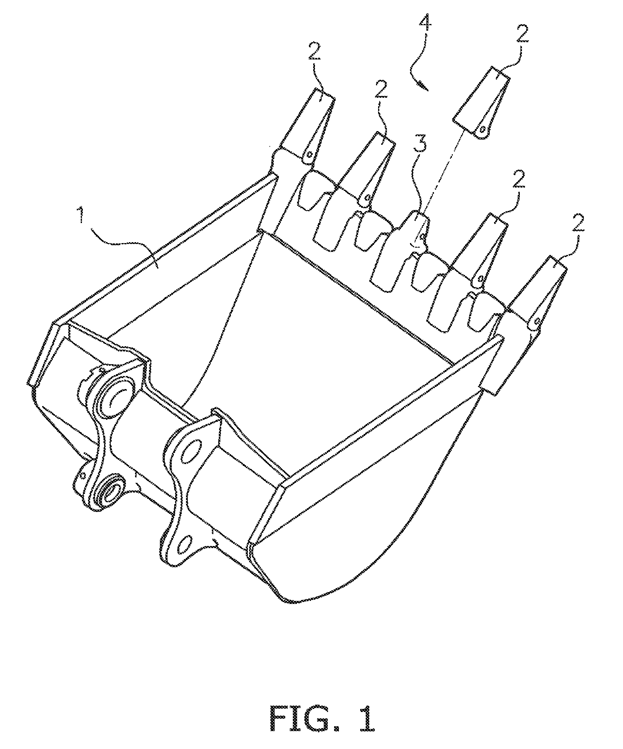
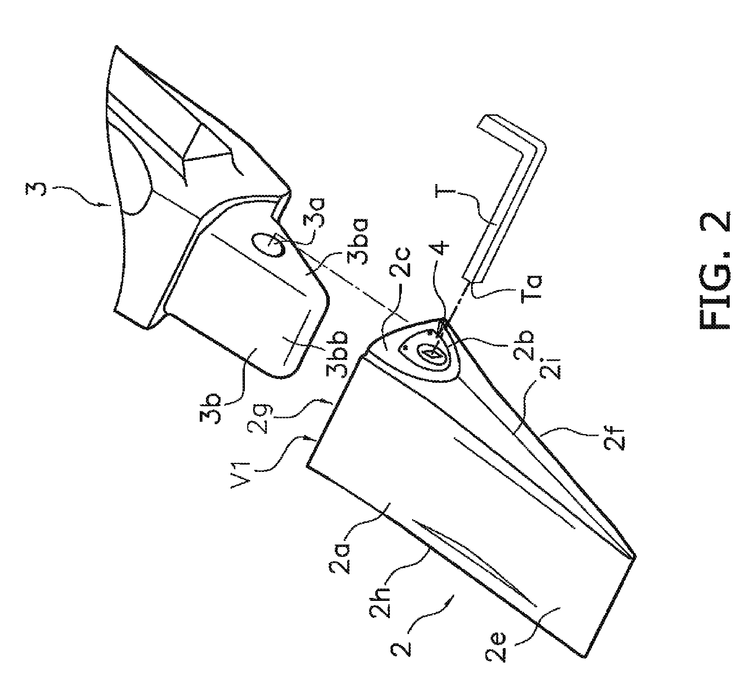
[0023]A tooth 2 pertaining to an embodiment of the present invention will be described through reference to FIGS. 1 to 4b, while also referring to the attachment structure to a bucket 1.

[0024]As shown in FIG. 1, the teeth 2 of a bucket 1 pertaining to this embodiment are attached to a plurality of adapters 3 provided to the distal end (the upper-right end in FIG. 1) of the lower face (the excavation side) of the bucket 1. These teeth 2 are replaced when they are worn down by work.

[0025]In this embodiment, a bucket tooth assembly corresponds to a tooth 2, and is an assembled part in which a latching member 4 is mounted to a main body part 2a (discussed below), and can be attached directly to an adapter 3 of the bucket 1.

Teeth 2

[0026]As shown in FIG. 2, the tooth 2 is a prong-like member attached to the distal end of the excavation portion of the bucket 1 in order to perform excavation with the bucket 1, and has a wedge-like outer shape that tapers toward the distal end. As shown in F...

second embodiment

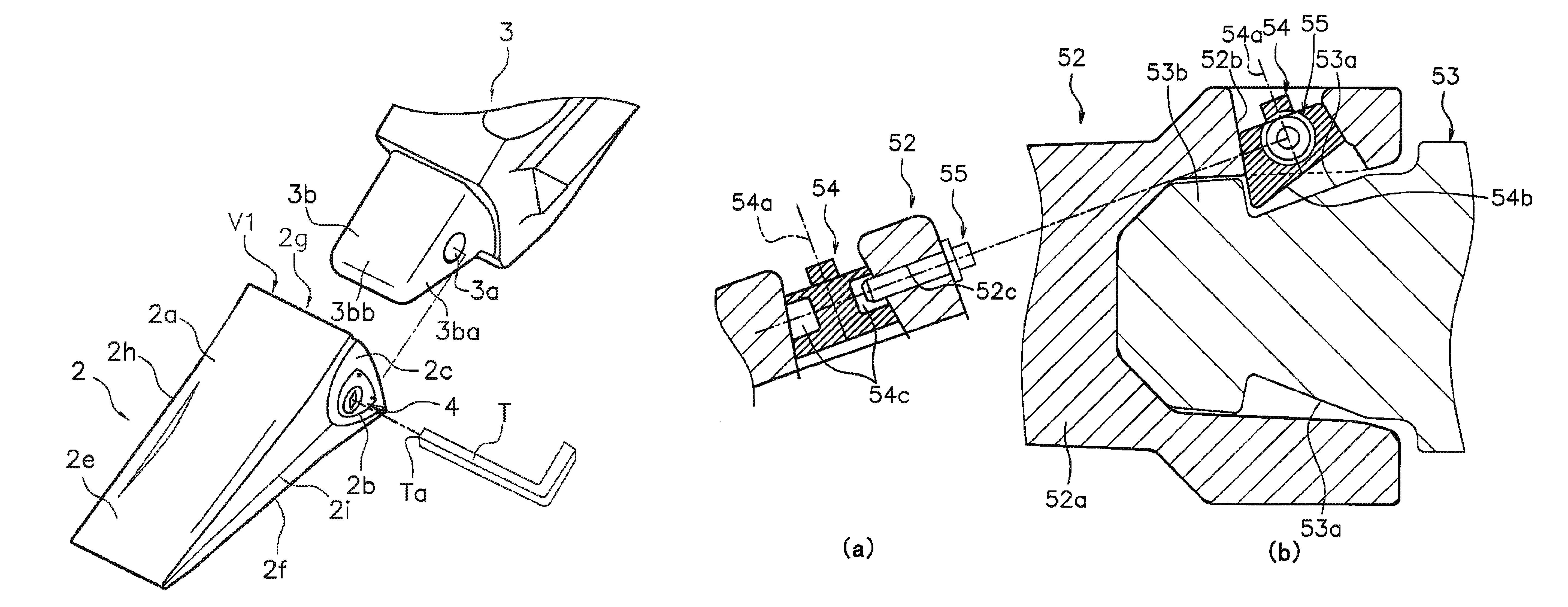
[0056]The teeth on a construction vehicle pertaining to another embodiment of the present invention will now be described through reference to FIGS. 5a and 5b.

[0057]In this embodiment, a bolt 55 (anti-rotation member) that stops rotation of a latching member 54. Which rotates around a rotational axis 54a and in the outer peripheral face of which is formed a groove 54e, is used as shown in FIGS. 5a and 5b instead of using the C-ring 5 of the above embodiment as an anti-rotation member that stops rotation of the latching member 4. This embodiment differs from the first embodiment above in that whereas in the first embodiment the opening of the through-hole had an opening bottom face, and a cross section of this opening was substantially shaped like a right triangle, in this embodiment the opening does not have a bottom face.

[0058]FIG. 5b is a detail cross section of the area around the latching member, in a plane that includes the width direction and the longitudinal direction of the...


PUM


Abstract

A bucket tooth for a construction vehicle includes a through-hole formed in a side wall part and passing through to a cavity. The through-hole has on a cavity side a rotating body hole having a shape of a truncated and rotated cone that remains after removing a large diameter side portion obtained by cutting diagonally to a rotational axis of the truncated and rotated cone with a large diameter side of the truncated and rotated cone being disposed on the cavity side, and with the rotational axis of the truncated and rotated cone being inclined outwardly toward the distal end portion of the bucket tooth from the cavity along a width direction of the bucket tooth.

Description

CROSS-REFERENCE TO RELATED APPLICATIONS[0001]This application claims priority to Japanese Patent Application No. 2011404556 filed on May 9, 2011, the disclosure of which is hereby incorporated herein by reference in its entirety.FIELD OF THE INVENTION[0002]The present invention relates to a bucket tooth that is mounted interchangeably to the distal end portion of the lower face of a construction vehicle bucket.DESCRIPTION OF THE RELATED ART[0003]Various kinds of excavation tool are attached to a work implement installed on a hydraulic excavator or other such work vehicle. For example, a plurality of teeth (excavation tools) are attached to the excavation-side distal end portion of a bucket (work implement) installed on a hydraulic excavator, so that the teeth protrude from the distal end portion. During excavation, these teeth function as cutting blades, which improves the excavation performance by biting into what is being excavated.[0004]Because the teeth attached to the distal en...

Claims


Application Information

Patent Timeline
Patent Type & Authority Patents(United States)
IPC IPC(8): E02F9/28
CPCE02F9/2816E02F9/2841E02F9/2833E02F9/2891E02F3/40E02F9/28
Inventor ITOU, DAIJIROUNAGATA, TAKANORIAMADA, EIJIYOSHIDA, TSUYOSHI
Owner KOMATSU LTD
Why Eureka
Try Eureka