
Vehicle seat having buckle holding structure

a technology for vehicle seats and buckles, applied in the direction of safety belts, operating chairs, pedestrian/occupant safety arrangements, etc., can solve the problem of inconvenient use of seat belt devices

Active Publication Date: 2010-06-08
HONDA MOTOR CO LTD
View PDF6 Cites 9 Cited by
  • Summary
  • Abstract
  • Description
  • Claims
  • Application Information

AI Technical Summary

Benefits of technology

[0012]According to the above described buckle holding structure, since the band is fixed to the rear end of the seat cushion, the band is not exposed to the seating surface of the seat cushion and thereby the appearance is good. Further, since the buckle is caught by the folded portion of the band, the buckle does not come off. In addition, since both ends of the band are fixed to the rear end of the seat cushion so as to be disposed in the width direction of the band, the width of a portion where the bands are extended in parallel with each other is increased. This portion where the bands are extended in parallel with each other becomes a receiving surface of the buckle when the buckle is lifted onto the seat cushion. Therefore, it is possible to reliably guide the buckle onto the seat cushion.
[0014]In this case, since the tongue piece of the seat cushion functions as the receiving surface of the buckle, it is possible to reliably guide the buckle onto the seat cushion.
[0019]According to the above-described vehicle seat, since the elastic bands draws the buckle onto the seat cushion in a process of transferring from the tip-up state to the seatable state, it is possible to reliably guide the buckle onto the seat cushion in the process of the transferring of the vehicle seat.

Problems solved by technology

If the buckle cannot be directly found when an occupant intends to fasten a seat belt, it is inconvenient to use the seat belt device.

Method used


Image

  • Vehicle seat having buckle holding structure
  • Vehicle seat having buckle holding structure
  • Vehicle seat having buckle holding structure

Examples


Embodiment Construction

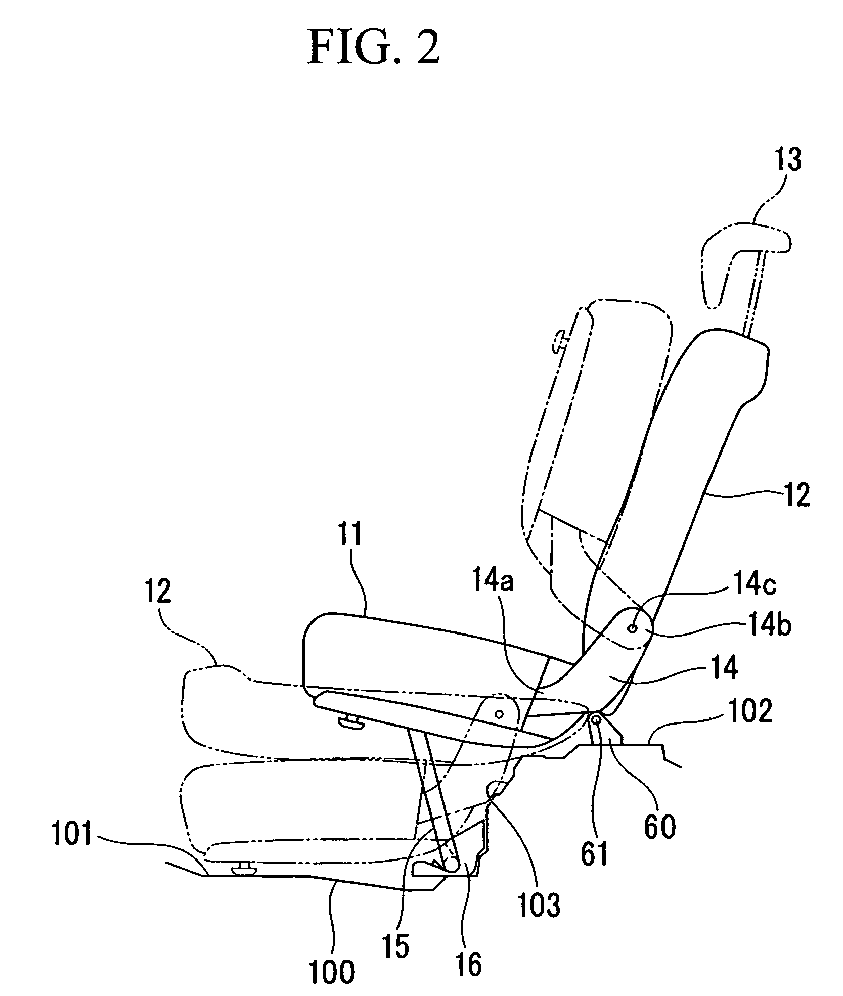
[0033]A buckle holding structure according to an embodiment of the present invention will be described below with reference to FIGS. 1 to 10. Note that, in the following description, an upward and downward direction indicates the upward and the downward direction of a vehicle body, a forward and backward direction indicates the forward and the backward direction of the vehicle body, and a left and right direction indicates the left and the right direction that corresponds to a vehicle width direction as seen from a driver's seat.

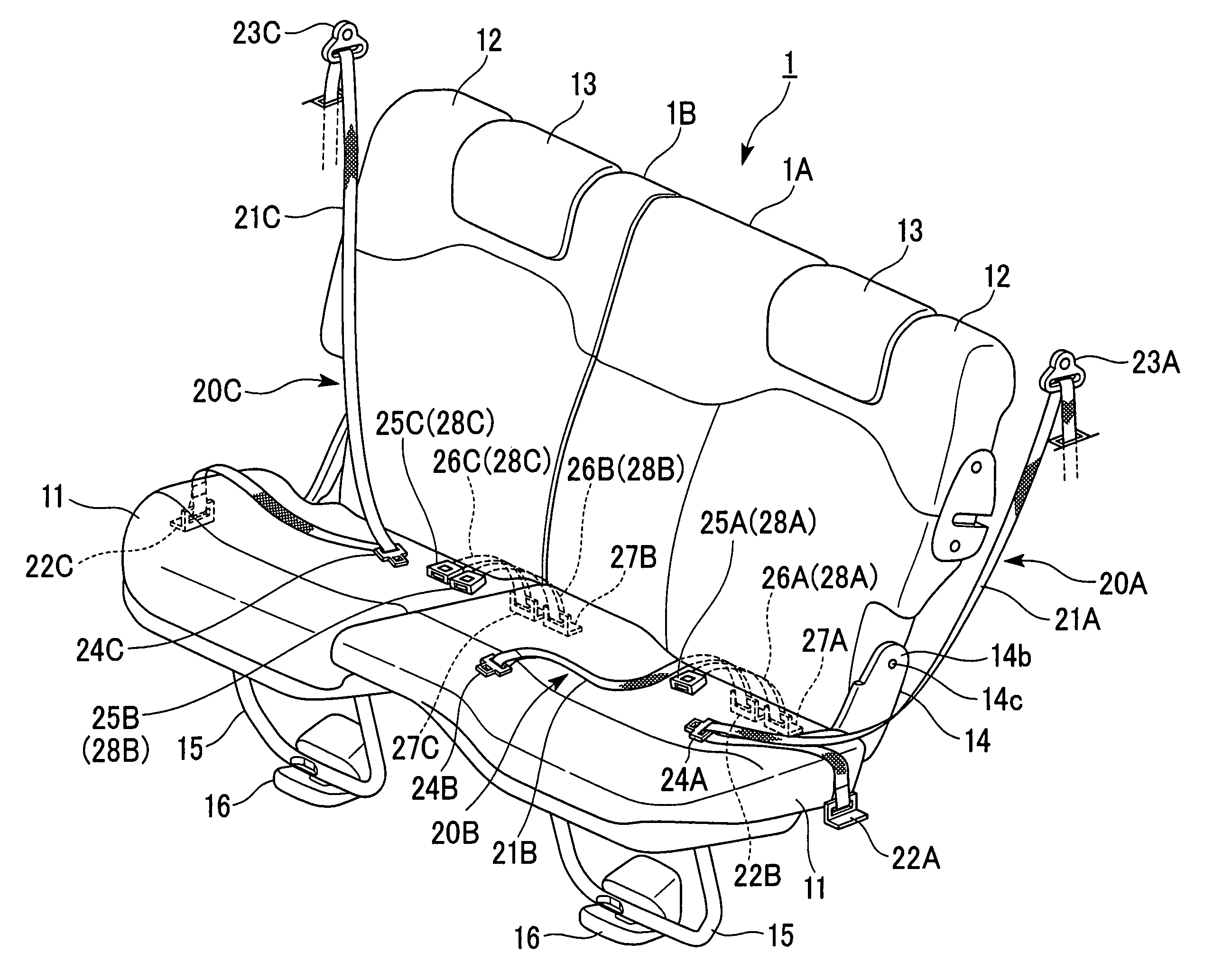
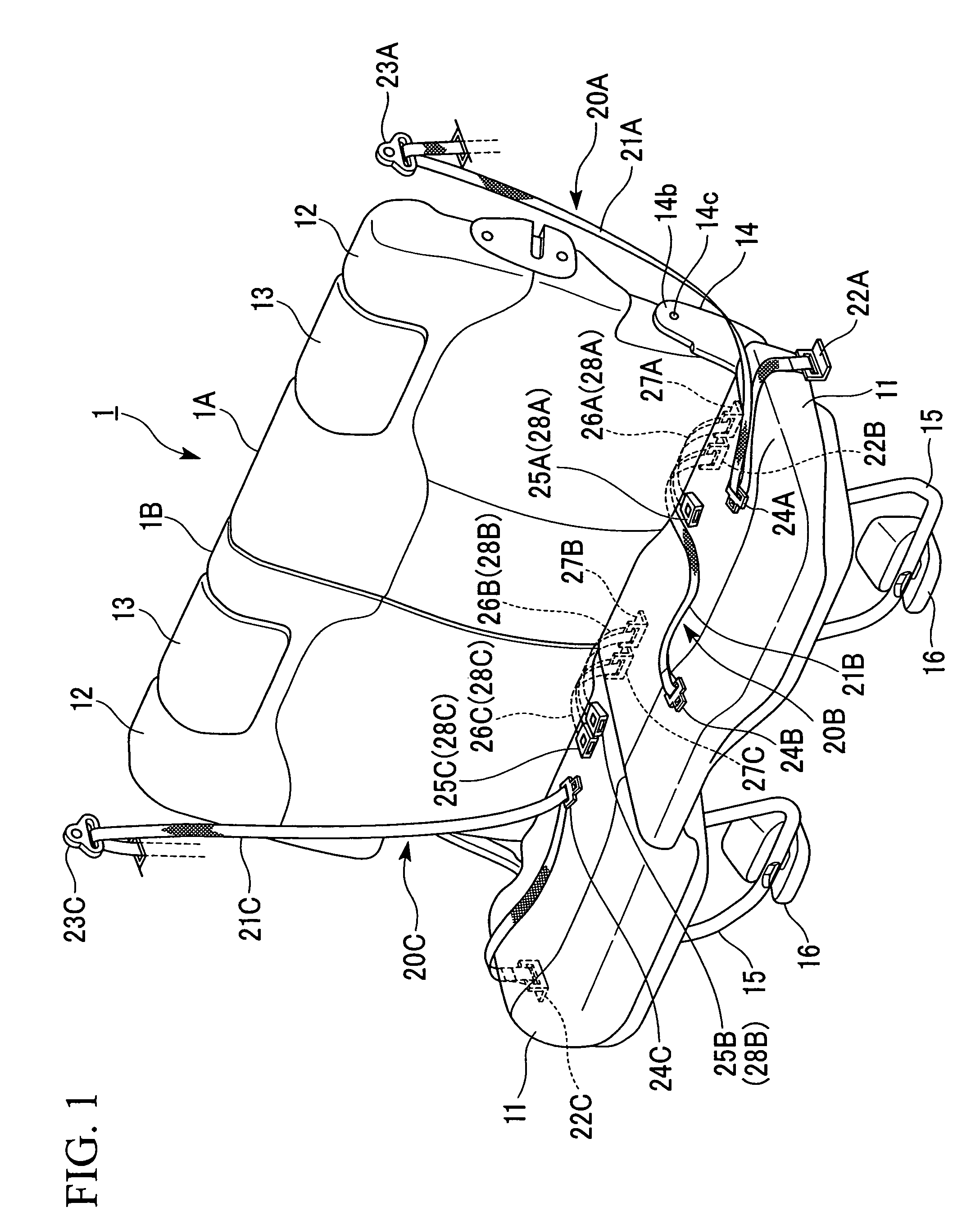
[0034]FIG. 1 is a perspective view showing the appearance of a rear seat 1 of a vehicle. The rear seat 1 is divided into two pieces at a predetermined ratio (for example, 7:3 or 6:4) so as to be composed of a left rear seat 1A having a larger width and a right rear seat 1B having a smaller width.

[0035]The structure common to the rear seats 1A and 1B will be described first. Each of the rear seats 1A and 1B includes a seat cushion 11 that supports occupant's ...


PUM


Abstract

A buckle holding structure for holding a buckle unit on a seat cushion, the buckle unit having: a belt of which one end is fixed to a vehicle body; and a buckle fixed to the other end of the belt, the buckle holding structure including: a band that has elasticity, has a predetermined width, and is folded in a U shape to form a folded portion, wherein both ends of the band are fixed to a rear end of the seat cushion so as to be disposed on the same plane in a width direction of the band; the belt of the buckle unit is inserted into a gap formed between both ends of the band, which is fixed to the rear end of the seat cushion, and the folded portion; and the buckle is caught by the folded portion.

Description

[0001]Priority is claimed on Japanese Patent Application No. 2007-237879, filed Sep. 13, 2007, the content of which is incorporated herein by reference.BACKGROUND OF THE INVENTION[0002]1. Field of the Invention[0003]The present invention relates to a buckle holding structure for a vehicle and a vehicle seat having the buckle holding structure.[0004]2. Description of Related Art[0005]There has been a seat belt device for a vehicle that restrains an occupant in a seat by engaging a tongue of a seat belt, which is stretched over an occupant's body, with a buckle of a buckle unit fixed to a vehicle body. Since the buckle unit is subject to a large impact during the collision, the buckle unit is fixed to the vehicle body. For example, one end of the belt is fixed to the vehicle body, and the buckle is fixed to the other end of the belt. If the buckle cannot be directly found when an occupant intends to fasten a seat belt, it is inconvenient to use the seat belt device.[0006]Accordingly, ...

Claims


Application Information

Patent Timeline
Patent Type & Authority Patents(United States)
IPC IPC(8): A47C31/00B60N2/44B60N2/90
CPCB60R22/02B60R2022/266B60R2022/021
Inventor TSUDA, TOSHIHIKOITO, TAKAHIRO
Owner HONDA MOTOR CO LTD
Learn More