Method for controlling sheet processing apparatus

a technology for processing apparatuses and sheets, applied in paper/cardboard containers, manufacturing tools, transportation and packaging, etc., can solve problems such as jamming and cutting failure of sheets, and achieve the effects of improving the operation efficiency of the sheet processing apparatus, increasing the normal conveying speed of sheets, and improving the operation efficiency

Active Publication Date: 2014-01-09
DUPLO SEIKO CORP
View PDF5 Cites 13 Cited by
  • Summary
  • Abstract
  • Description
  • Claims
  • Application Information

AI Technical Summary

Benefits of technology

[0021]The first invention of the present invention is as follows:
[0022](1) When sheet conveying direction length (Lr) of rear end cut region (Sr) of the sheet is long, the sheet is finely cut and divided into predetermined fine-cutting unit length (Lr0) sequentially from the sheet conveying downstream end of rear end cut region (Sr) to be discharged. Therefore, not only the cut strip cut into predetermined fine-cutting unit length (Lr0), but also the cut strip in rearmost end divided region (Sr1) which is left last, can be immediately discharged downward from between the cutting mechanism and the pair of first conveying rollers on the sheet conveying upstream side without being stayed. With this, sheet jamming, sheet damaging, and discharging of the cut strip into the sheet receiving section together with the product can be eliminated.
[0023](2) To improve the operation efficiency of the sheet processing apparatus, it is necessary to increase the normal conveying speed of the sheet. However, even when the normal conveying speed is increased, the conveying speed of the pair of first conveying rollers on the sheet conveying upstream side is only temporarily lowered to solve the problems. Therefore, the problems can be solved while the operation efficiency can be improved.
[0024](3) While the cutting mechanism is held opened, the pair of first conveying rollers on the sheet conveying upstream side are only controlled at the speed lower than the normal conveying speed. Therefore, it is unnecessary to add any special mechanisms, so that the cost can be lowered.
[0025](4) According to configuration (a), the lower conveying roller of the pair of first conveying rollers on the sheet conveying upstream side is a driving roller. Therefore, the lower conveying roller on the driving side can reliably guide the sheet conveying upstream edge of the cut strip in rearmost end divided region (Sr1) downward.
[0026](5) According to configuration (b) the cut strip cut into predetermined fine-cutting length (Lr0) can be reliably discharged downward from between the cutting mechanism and the pair of second conveying rollers.

Problems solved by technology

These phenomena cause sheet jamming and cutting failure.

Method used


Image

  • Method for controlling sheet processing apparatus
  • Method for controlling sheet processing apparatus
  • Method for controlling sheet processing apparatus

Examples


Embodiment Construction

[0066][The Embodiment of a First Invention]

[0067]“The Overall Configuration of a Sheet Processing Apparatus”

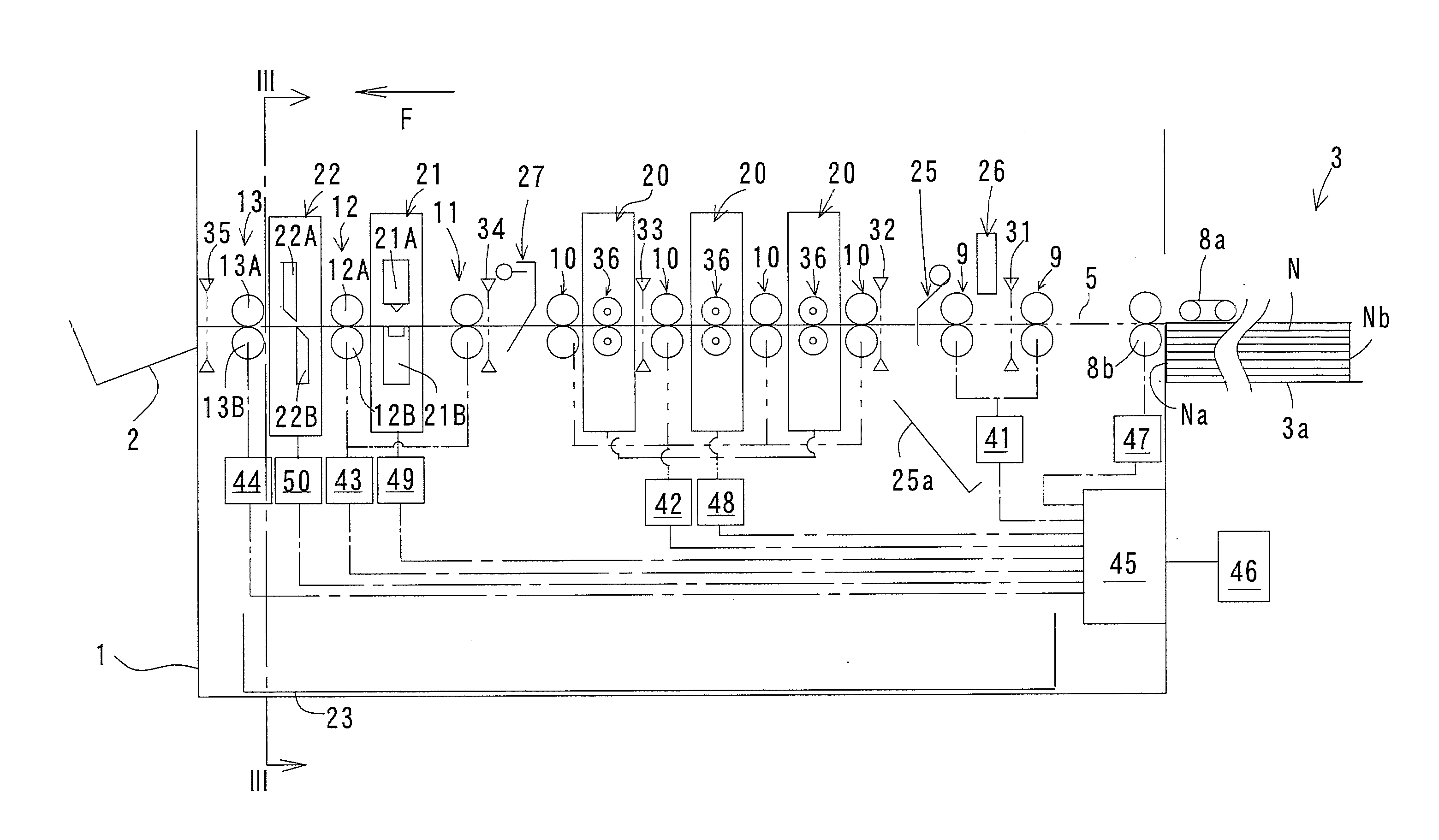
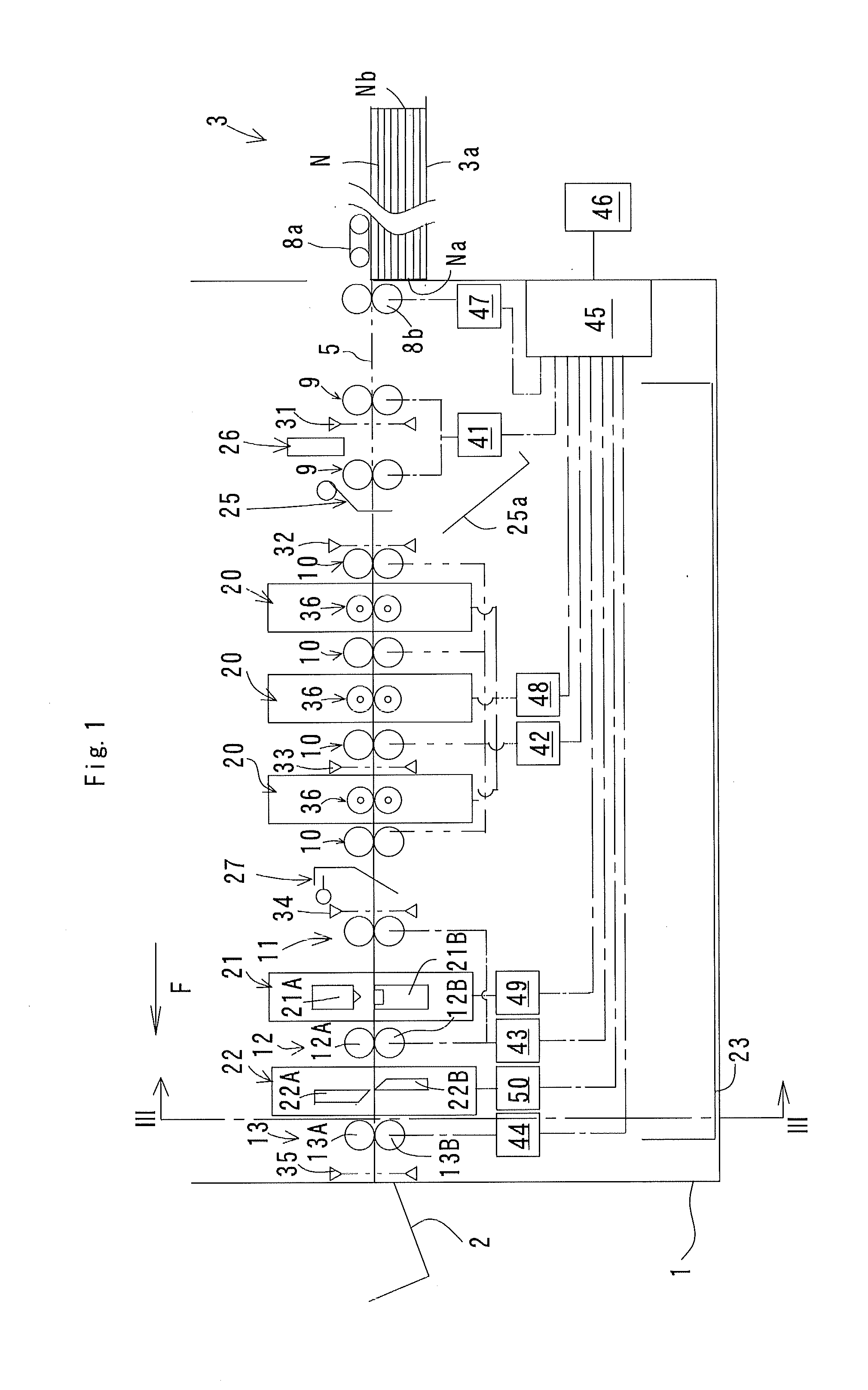
[0068]FIG. 1 is a schematic longitudinal sectional view of a sheet processing apparatus using a controlling method according to a first invention of the present invention. In FIG. 1, the sheet processing apparatus includes a sheet receiving section 2 at the downstream end in sheet conveying direction F in an apparatus body 1, a sheet feeding section 3 at the upstream end in sheet conveying direction F therein, and a substantially horizontal conveying path 5 between the sheet feeding section 3 and the sheet receiving section 2. A suction conveying belt mechanism 8a and a feeding roller 8b are arranged in the sheet feeding section 3. On the conveying path 5, a plurality of pairs of conveying rollers 9, 10, 11, 12, and 13 are spaced in sheet conveying direction F, and slit forming mechanisms 20, a fold forming mechanism 21, and a cutting mechanism 22 are arranged as processing me...


PUM


Abstract

In the control of a cutting mechanism of a sheet processing apparatus, when rear end cut region of a sheet is finely cut and divided into predetermined fine-cutting unit length, if sheet conveying direction length of rearmost end divided region is equal to or more than minimum reference length corresponding to the distance between cutting position of the cutting mechanism and nipping position of a pair of first conveying rollers and is less than maximum reference length in which predetermined fine-cutting unit length is added to minimum reference length, upper and lower blades of the cutting mechanism are held opened immediately after the downstream edge of rearmost end divided region is cut and the pair of first conveying rollers are driven at limited conveying speed lower than normal conveying speed.

Description

TECHNICAL FIELD[0001]The present invention relates to a method for controlling a sheet processing apparatus. More specifically, the present invention relates to a method for controlling a sheet processing apparatus having a cutting mechanism which cuts a sheet in a direction orthogonal to a sheet conveying direction.BACKGROUND ART[0002]A sheet processing apparatus has been developed which combines, as needed, a cutting mechanism, a slit forming mechanism which cuts a sheet in parallel with a sheet conveying direction, and a fold forming mechanism which forms a fold onto the sheet, by cassetting.[0003]FIG. 27 shows a cutting mechanism of a sheet processing apparatus. A cutting mechanism 201 includes an upper movable blade 201a, and a lower fixed blade 201b. The upper movable blade 201a is driven to be raised and lowered to cut sheet N at cutting position P1 in a direction orthogonal to sheet conveying direction F. A pair of conveying rollers 202 including an upper conveying roller 20...

Claims


Application Information

Patent Timeline
Patent Type & Authority Applications(United States)
IPC IPC(8): B65H35/00
CPCB65H35/0006B26D1/085B26D5/20B26D2001/0066B26D5/007B23Q15/00
Inventor MAEDA, TAKAAKITOKI, AKIHIKOOTA, SATOSHIKOSAKA, SHUHEIFUNASE, MASASUKE
Owner DUPLO SEIKO CORP
Why Eureka
Try Eureka