Disposable flexible reamer shaft for medical applications

a flexible, reamer shaft technology, applied in the field of surgical reamers, can solve the problem of local concentration and other problems, and achieve the effects of reducing heat buildup, promoting rapid bone healing, and preventing damage to bone tissu

Active Publication Date: 2013-08-27
LRS SCI & TECH LLC
View PDF15 Cites 14 Cited by
  • Summary
  • Abstract
  • Description
  • Claims
  • Application Information

AI Technical Summary

Benefits of technology

[0022]The attachment of the modular tapered, cylindrical or spherical, hollow or solid, reamer to the distal end threads of the disposable flexible reamer shaft is a single point attachment and relies on the threaded length provided to maintain local concentricity of the shaft. Since the shaft is flexible, the only issue that matters is the local concentricity. The surgeon can reliably guide the shaft along any orientation as long as the reamer follows exactly the orientation selected by the surgeon. In such cases, the reamer aim point is precisely determined by the insertion point of the guide pin within the bone cavity. This process of orienting the shaft and the reamer is aided by the previously inserted guide pin in the bone cavity, so that the surgeon can readily orient the reamer within the bone cavity. The flexible shaft may be used for creating a fresh bone cavity or for enlarging an existing bone cavity.
[0023]When a modular hollow reamer is used with the flexible shaft, it captures the bone debris and moves it away from the cutting location, thereby reducing heat build up at the reaming surface. This prevents damage to bone tissue and promotes rapid bone healing. Since the shaft is a low-cost construction, it can be disposed off readily, thus preventing cross contamination.
[0027]iii. the male element screw threads being counter clockwise, thereby preventing loosening of the modular reamer during the bone reaming procedure;

Problems solved by technology

Since the shaft is flexible, the only issue that matters is the local concentricity.

Method used


Image

  • Disposable flexible reamer shaft for medical applications
  • Disposable flexible reamer shaft for medical applications
  • Disposable flexible reamer shaft for medical applications

Examples


Embodiment Construction

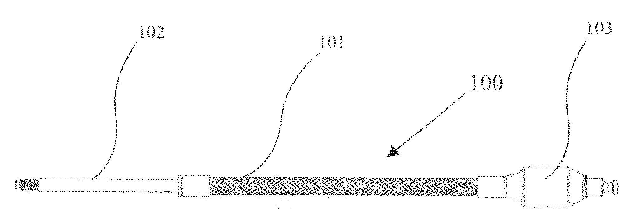
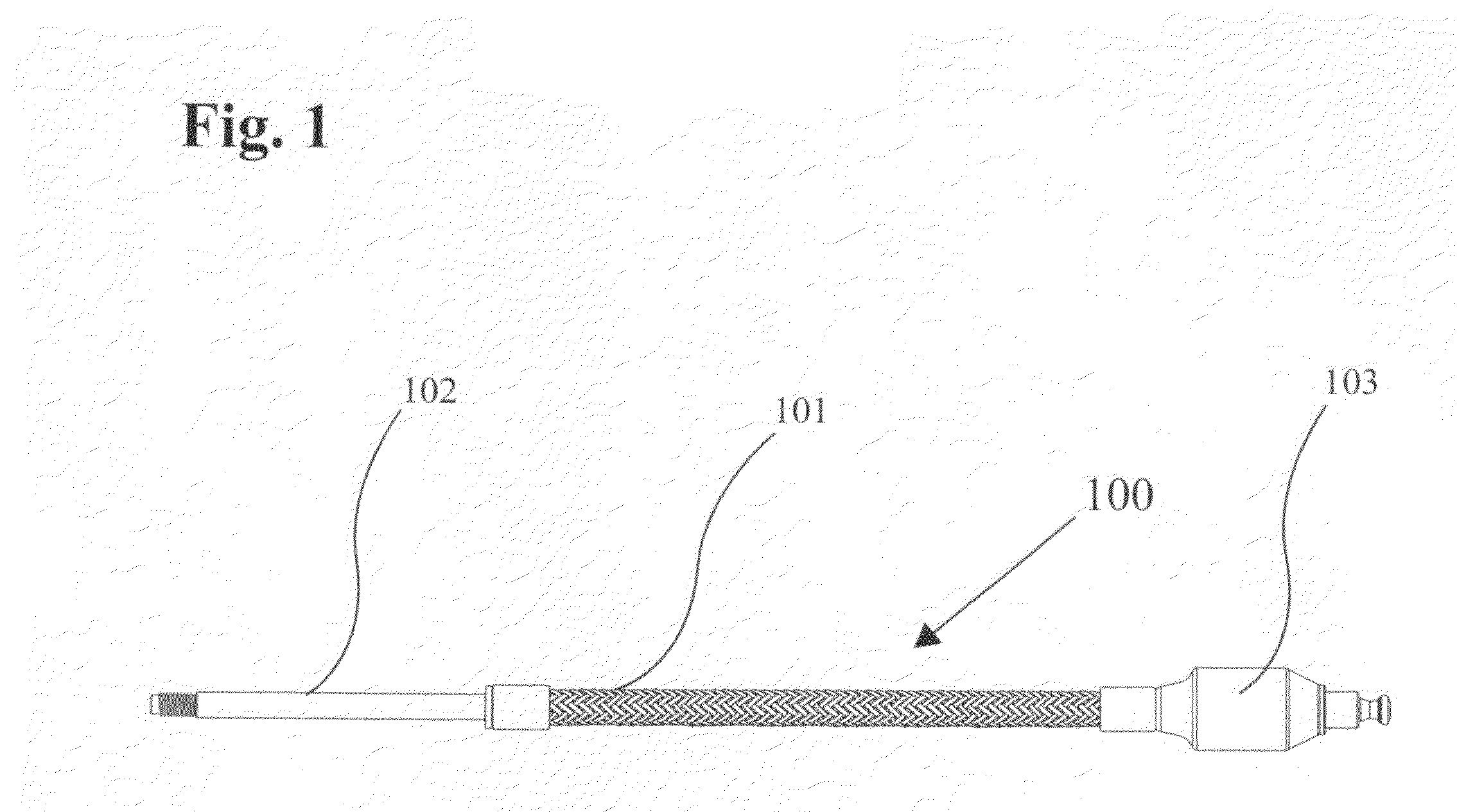
[0039]In orthopedic surgery, many surgical procedures require the need to ream the internal cavity of long bones. These include fracture procedures and total hip procedures. In the current technology, rigid solid reamers and flexible reamers are used for preparing the bone canals for implants. These reamers can be one-piece construction and also modular allowing for the cutting head to be removed and different diameter sizes attached. Cutters can become dull even after one use and the option to discard the cutter would provide a significant benefit for the surgeon and the patient. It would assure that the cutters are always sharp and clean for each patient.

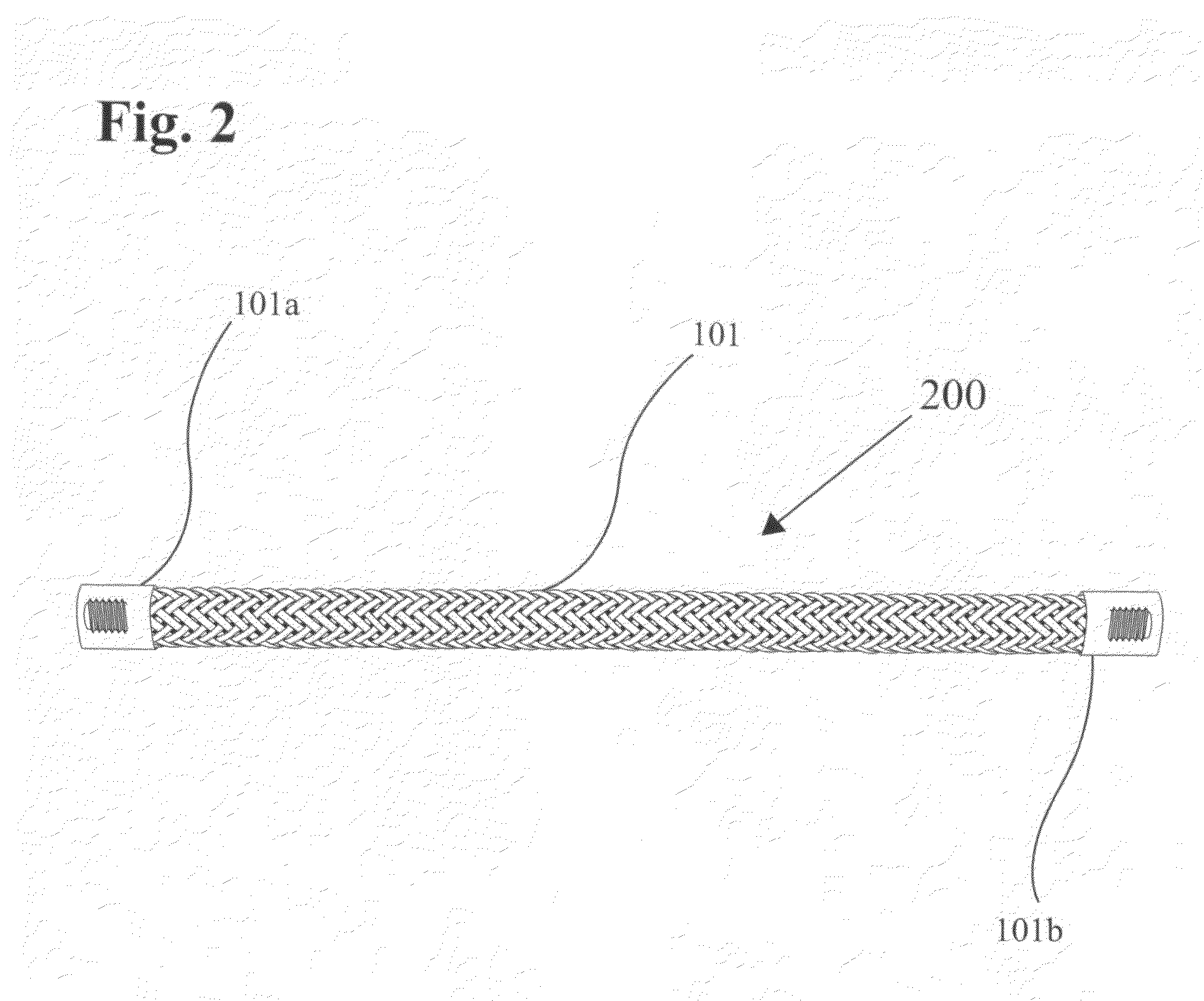
[0040]The reamer shafts, especially flexible shafts, which are designed to drive these cutters are typically reused. Although the sharpness of cutting teeth is not an issue, the ability to properly clean these reamer shafts is an issue. Many of the reamer shafts are cannulated with a small hole running down the center of the shaft...


PUM

PropertyMeasurementUnit
outer surface diameteraaaaaaaaaa
lengthaaaaaaaaaa
lengthaaaaaaaaaa

Abstract

A low cost disposable flexible reamer shaft has a flexible cylindrical braided tube shaft with an outer diameter in the range of 4 to 14 millimeters and 250 to 400 mm length, and a central aperture for insertion of a flexible polymeric tube. The braided tube shaft is permanently attached to a first end element and a second end element. The threaded end of the first end element attaches to female threads of modular tapered, cylindrical or spherical, hollow or solid reamer assembly. The second end element fits into a chuck of a drive motor. The threaded attachment of the first end provides local centerline matching. A guide pin is inserted in the bone cavity, which enters the reamer. The central aperture of the flexible polymeric tube provides centerline matched, wobble-free reaming. The reaming end point is precisely the guide pin inserted location while the reaming direction is controlled by the surgeon by flexing the flexible reamer shaft.

Description

[0001]This is a Continuation-In-Part of application Ser. No. 12 / 583,873, filed on Aug. 27, 2009 for “Disposable Reamer Shaft For Modular, Spherical, or Tapered Hollow Reamer Assembly For Medical Applications” which, in turn, is a Continuation-In-Part of application Ser. No. 12 / 072,671, filed on Feb. 27, 2008 for “Modular Spherical Hollow Reamer Assembly For Medical Application” which is a Continuation-In-Part of application Ser. No. 11 / 973,260, filed Oct. 5, 2007 for “Modular Tapered Hollow Reamer For Medical Applications” which, in turn, is a Continuation-In-Part of application Ser. No. 11 / 704,754, filed Feb. 9, 2007, the disclosures of which are hereby incorporated in their entirety by reference thereto.BACKGROUND OF THE INVENTION[0002]1. Field of the Invention[0003]The present invention relates to surgical reamers that create bone cavities; and, more particularly, to a flexible disposable reamer shaft that may be attached to a modular disposable spherical or tapered hollow reamer...

Claims


Application Information

Patent Timeline
Patent Type & Authority Patents(United States)
IPC IPC(8): A61B17/00
CPCA61B17/1631Y10T29/49826
Inventor SIDEBOTHAM, CHRISTOPHER G.LEWIS, RANDALL J.ROITBURG, LEON
Owner LRS SCI & TECH LLC
Why Eureka
Try Eureka