

Valve position indicator
A technology for indicators and valves, which is applied in the direction of valve devices, rotation vibration suppression, engine components, etc., can solve the problems of damage to the rotation shaft components, vibration of the valve shaft, and failure to meet actual needs, etc., to extend the service life and maintain the same The effect of axis
Active Publication Date: 2012-08-01
SHENYANG NORTHEAST ELECTRIC POWER CONTROL
View PDF4 Cites 1 Cited by
- Summary
- Abstract
- Description
- Claims
- Application Information
AI Technical Summary
Problems solved by technology
Since the rotating shaft and the valve shaft are rigidly connected, the valve shaft will vibrate under normal working conditions, which will damage the travel switch on the rotating shaft and the internal components of the potentiometer, and affect the service life of the valve position indicator
If there is a deviation in the coaxiality between the rotating shaft and the valve shaft, it cannot be automatically eliminated; secondly, the valve position indicator can only display the valve opening and closing positions, which cannot meet actual needs
Method used
View moreImage
Smart ImageViewing Examples

Examples
Embodiment Construction
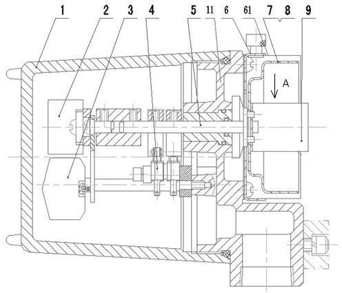
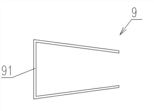
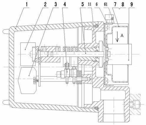
[0009] The travel switch 4 and the potentiometer 2 are installed on the rotating shaft 5, and the rotating shaft is installed on the bracket 11 in the casing 1 through a bushing or a bearing. The elastic clip 9 is groove-shaped, and its section is dovetail-shaped. Fixed on the rotating shaft with the jaws facing outwards.
[0010] Horn-shaped dial 7 is also fixed on the rotating shaft, scale 8 is attached to the outside of dial, window 6 is fixed on the housing, window 61 is established on the window, facing the scale, not only may display valve opening and closing It can also quantitatively display the valve position and angle. 3 is a connection terminal.
Login to View More PUM
 Abstract
The invention provides a valve position indicator, and aims to solve the technical problems that the valve position indicator is in rigid connection with a valve shaft and the valve shaft generates vibration under a normal working condition, so a travel switch and components in a potentiometer can be damaged, and the service life of the valve position indicator is shortened. The key points of the invention are that: the travel switch and the potentiometer are arranged on a rotating shaft; the rotating shaft is arranged on a support in a shell; an elastic clip is groove-shaped, and the cross section of the elastic clip is dovetail-shaped; and a base plate of the elastic clip is fixed on the rotating shaft, and the opening of the clip faces outwards. The valve position indicator has the advantages that: the elastic clip is elastically connected with the valve shaft and can compensate the vibration of the valve shaft, so that the service life of the valve position indicator is greatly prolonged.
Description
technical field [0001] The invention relates to a valve position indicator. Background technique [0002] Valve position indicators include travel switches and potentiometers, etc., installed on the rotating shaft, and are used for display and feedback of the position of angular stroke valves such as ball valves. Since the rotating shaft and the valve shaft are rigidly connected, the valve shaft will vibrate under normal working conditions, which will damage the travel switch on the rotating shaft and the internal components of the potentiometer, and affect the service life of the valve position indicator. If there is a deviation in the coaxiality between the rotating shaft and the valve shaft, it cannot be eliminated automatically; secondly, the valve position indicator can only display the valve opening and closing positions, which cannot meet actual needs. Contents of the invention [0003] In order to solve the above technical problems, the present invention provides ...
Claims
Login to View More Application Information
Patent Timeline
 IPC IPC(8): F16K37/00F16F15/12F16F15/04
Inventor刘宝军郑学明刘观华孙贤双雷利聂强徐进善
OwnerSHENYANG NORTHEAST ELECTRIC POWER CONTROL