Apparatus for holding a container

a container and accessory technology, applied in the field of accessories for holding containers, can solve the problems of container failure to seat properly, restrict the ability to provide a holder of a larger diameter, and constrain the design of the centralising featur

Active Publication Date: 2016-06-14
CROWN PACKAGING TECH
View PDF17 Cites 2 Cited by
  • Summary
  • Abstract
  • Description
  • Claims
  • Application Information

AI Technical Summary

Benefits of technology

[0015]According to another aspect of the present invention, there is provided a method of holding a cup-shaped article in a concentric position, the method comprising: supplying, removing or balancing air pressure such that when suction is applied to the article, the article is held against a seating face of a holder; and characterised by: preventing radial movement of the article with a concentric outer sleeve and thereby maintaining concentricity of the article; and moving the outer sleeve into a retracted position and releasing the article from the seating face.
[0017]A step of supplying compressed air may aid release of the article from the seating face.

Problems solved by technology

Whilst this is suitable for forming complex shapes, such shaping requires complex blow forming machinery and is not always be needed for holding a can when carrying out more simple rotational operations.
However, machine motion often limits the ability to provide a holder of a larger diameter than the container, which constrains the design of the centralising feature.
Without this clearance, the container can fail to seat properly on the flat face, and this may impair the seal or cause it to rock on the holder.
Unfortunately, this clearance can lead to non-concentrical holding of the container or article and allows sideways / radial movement of the article.
If seal or grip is lost due to improper seating of the container or cup-shaped article, then manufacturing defects can occur.
If grip is lost in a cap or can flanging or curling operation, an incomplete or uneven flange or curl results.
Similarly, if grip is lost in a lining operation, a defective lining is created.

Method used


Image

  • Apparatus for holding a container
  • Apparatus for holding a container
  • Apparatus for holding a container

Examples


first embodiment

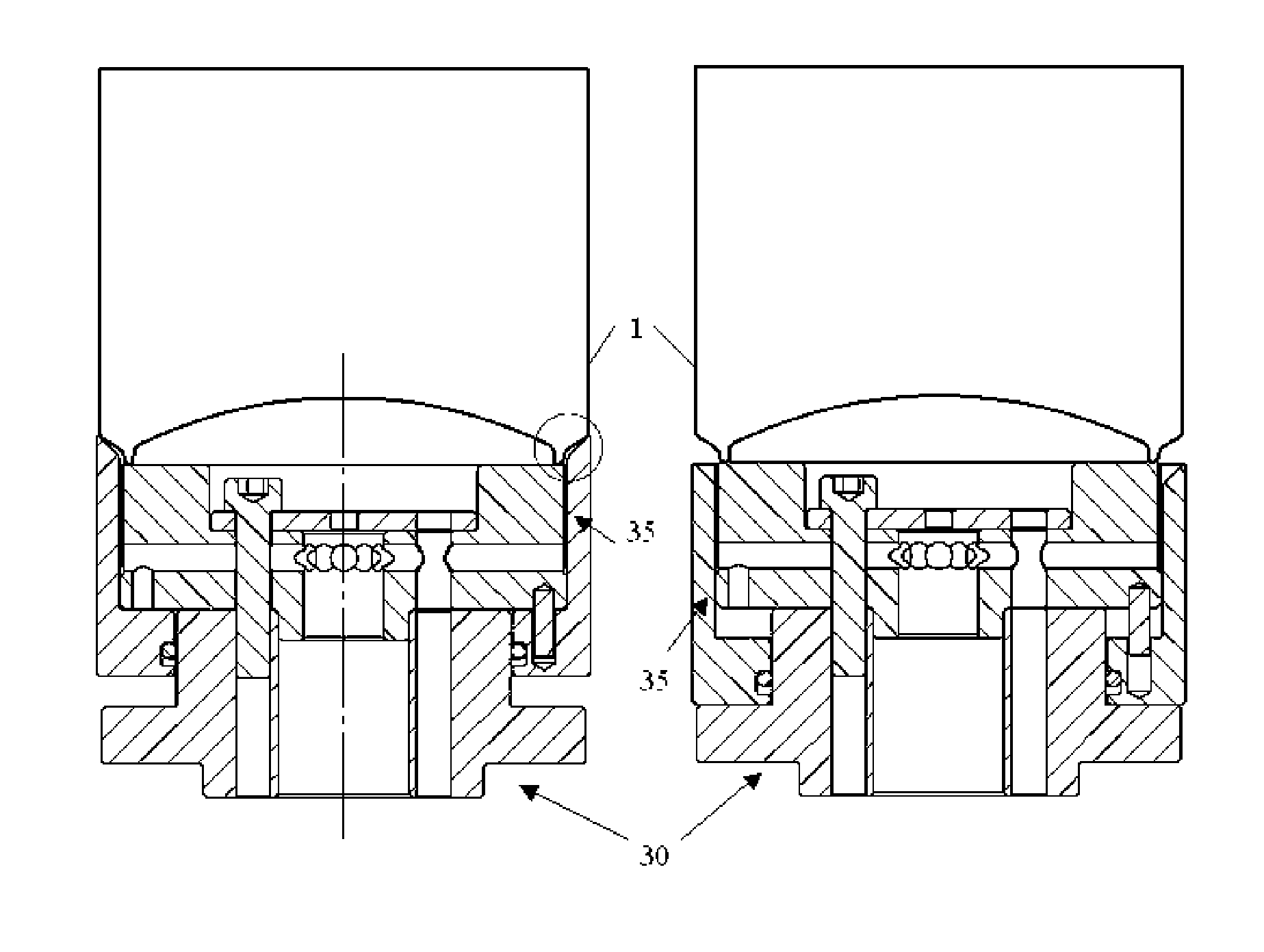
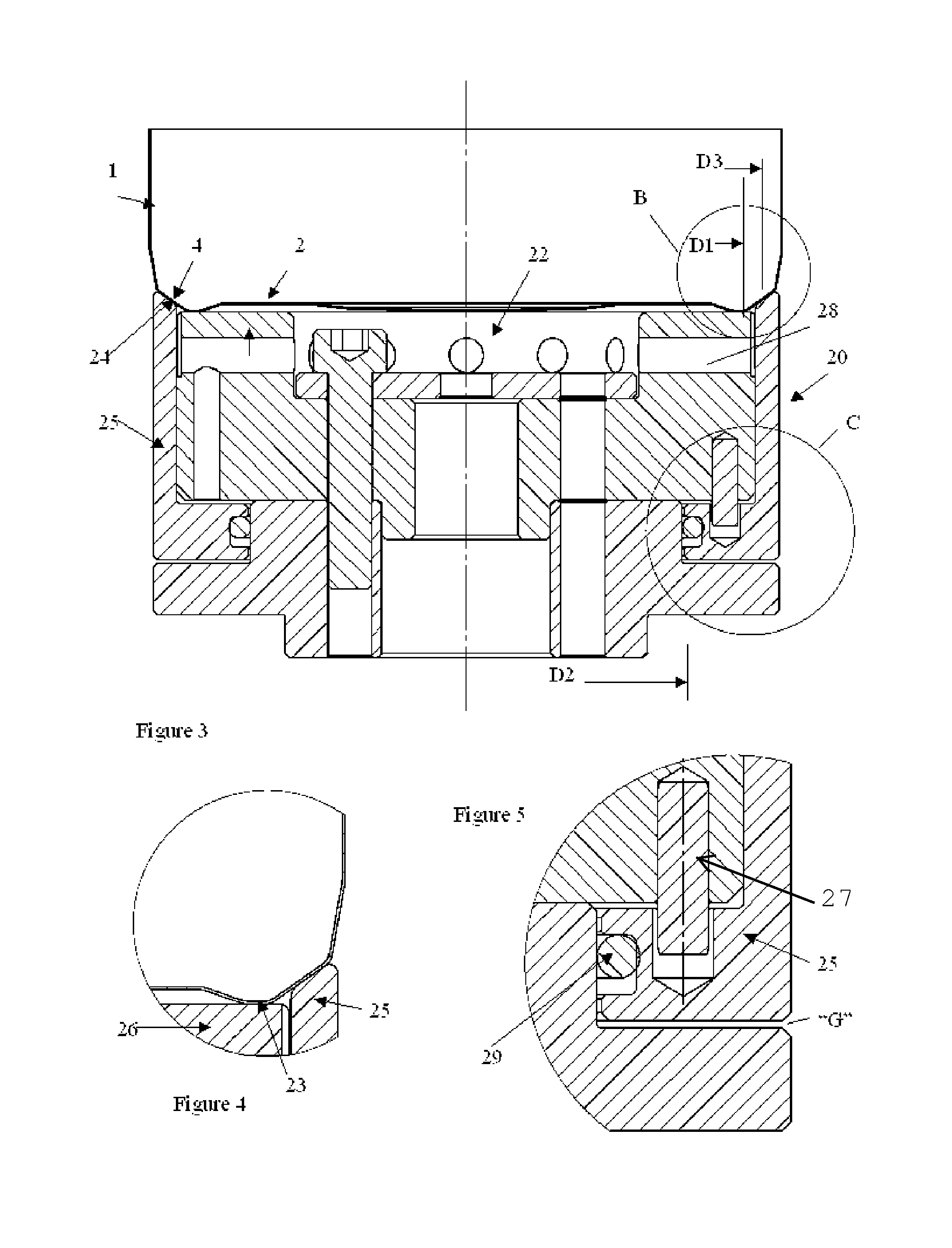
[0033]A holding apparatus 20 according to the present invention is shown in FIGS. 3 to 5. Similarly to the prior art holder of FIGS. 1 and 2, the holding apparatus 20 of FIGS. 3 to 5 comprises a central region 22 which serves to accommodate the centre of the cup base 2, and any shape, button or protrusion on the cup base 2.

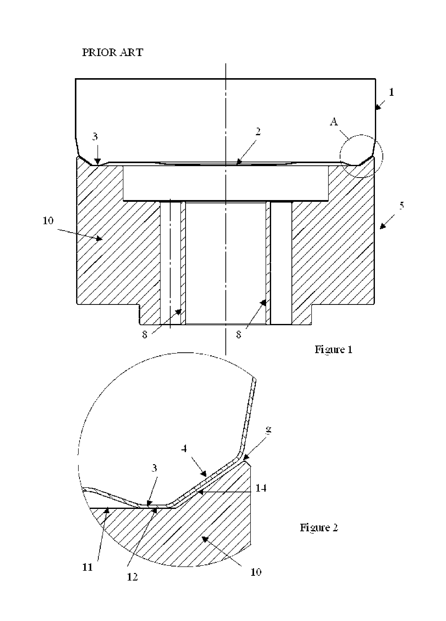
[0034]In contrast to the prior art, however, the holding apparatus 20 has an independent outer sleeve 25, which is slidable in an axial direction relative to central region 22. FIG. 3 shows the sleeve in its forward position, in which conical upper edge 24 fully engages and grips inclined portion 4 of drawn cup 1 (best seen from FIG. 4). This is in contrast with the holder of the prior art, which as noted above, is always spaced from the inclined portion 4 (see enlarged section of FIG. 2).

[0035]Often the operation such as cutting or forming imparts a torque on the article and is therefore advantageous that the sleeve of the holder of the present invention grips th...

second embodiment

[0040]the invention is shown in FIGS. 6 to 8. In this embodiment, the outer sleeve is able to slide to a position, which is level with or below the seating face of the holder. This enables the article to be slid easily into position. Applying suction will raise the outer sleeve into contact with the article to be held, and applying compressed air will lower the outer sleeve to allow the article to be slid into or away from the holder.


PUM


Abstract

The apparatus comprises holder (20) with a seating face on which a container such as a cupshaped article (1) stands. Air is supplied through channels and air pressure is balanced so as to hold the article (1) against the face. The profile of the apparatus guides a base feature, or “stand” of the article (1) into the holder (20) and onto the seating face (23), and contacts the article (1) radially outside the seating face (23). The apparatus also has a concentric outer sleeve (25) to provide the additional radial contact and resist lateral movement of the article (1) while maintaining concentricity.

Description

CROSS-REFERENCE TO RELATED APPLICATIONS[0001]This application is the National Stage of International Application No. PCT / EP2012 / 053826 filed Mar. 6, 2012, which claims the benefit of EP application number 11158968.5, filed Mar. 21, 2011, the disclosures of which are incorporated herein by reference in their entirety.TECHNICAL FIELD[0002]This invention relates to an apparatus for holding a container. In particular, but not exclusively, the invention relates to an apparatus and method for holding a container or cup-shaped article such as a metal can body, container lid or closure, whilst performing operations on the sidewall or rim of the container. Examples of such operations include cutting or forming the sidewall or rim of the container or applying a material such as a coating, decoration or lining.BACKGROUND ART[0003]EP 0853515 B (CROWN CORK & SEAL TECHNOLOGY CORP.) is a blow forming apparatus in which a whole can body is held in a three part movable mould: base, centre and top pa...

Claims


Application Information

Patent Timeline
Patent Type & Authority Patents(United States)
IPC IPC(8): B25B11/00B21D51/26
CPCB21D51/26B21D51/2692B25B11/005
Inventor DUNWOODY, PAUL ROBERT
Owner CROWN PACKAGING TECH
Why Eureka
Try Eureka