Biochip and a manufacturing method of biochip

a biochip and manufacturing method technology, applied in the field of biochips, can solve the problems of poor detection accuracy, inability to complete separation, and lower detection accuracy, so as to reduce the width of the sample introductory passage, improve detection accuracy, and reduce the width of the sample band

Inactive Publication Date: 2007-06-12
PRESIDENT OF SHIZUOKA UNIVERSITY +1
View PDF13 Cites 10 Cited by
  • Summary
  • Abstract
  • Description
  • Claims
  • Application Information

AI Technical Summary

Benefits of technology

[0069]Further, where the taper sections are formed in the sample introductory passage of the platy member, so that the width of the sample introductory passage is gradually reduced toward an intersection part with the sample separation passage, it is possible to gather the sample in a narrow space so as to reduce the width of band of sample supplied to the sample separation passage, and accordingly the detection accuracy may improve.
[0070]Further, where the positioning portions are provided, for positioning of the biochip when being installed in an electrophoresis apparatus, the installation may be facilitated.
[0071]Further, where there is provided a platy member, which receives a sample in a sample separation passage via an injection hole, and discharges the sample via a discharge hole, and where there is provided a seal member, connected to the platy member, and having a sample introductory nozzle at a position corresponding to the injection hole, and with another discharge hole at a position corresponding to the discharge hole of the platy member, thereby the sample may be directly introduced in the sample separation passage, without requiring the sample introductory passage, via the injection hole of the sample introductory nozzle provided in the seal member on the side of the platy member, such structure will have the merit in that, the structure, in particular that including the electric power supply, may be remarkably simplified.
[0072]In this case, where the sample introductory nozzle is in taper form so that the diameter of the sample introductory nozzle is gradually reduced in the direction of thickness of the seal member toward the platy member, the width of band supplied to the sample separation passage may be reduced by gathering the sample in a narrow space, thereby it is possible to improve the detection accuracy.
[0073]Further, by providing the electrophoretic electrode, it is possible to surely carry out the dropping of a very little amount of sample.
[0074]In this case, where the positioning portions are similarly provided, for positioning of the biochip when being installed in an electrophoresis apparatus, the installation may also be facilitated.

Problems solved by technology

At that time, during movement of the sample, the width of the band of sample existing at the intersection part will be expanded due to molecular diffusion, thereby the detected image of electrophoresis will become unclear, which would result in a poor detection accuracy.
In particular, the larger the number of base becomes (such as DNA), the lower the detection accuracy would become, and due to the difference of base number, the complete separation cannot be done.
Thus, even a sufficient volume of sample is injected from the liquid reservoir sections, the amount of sample, actually entering the sample separation passage to be used for separation, is very little, and the large amount of the sample, i.e. the remaining sample, will become useless.
In addition, as discussed above, since the two-phase electrophoresis, i.e. the introductory electrophoresis and the separation electrophoresis is required, the apparatus related to the electric power supply would become complicated.

Method used


Image

  • Biochip and a manufacturing method of biochip
  • Biochip and a manufacturing method of biochip
  • Biochip and a manufacturing method of biochip

Examples


first embodiment

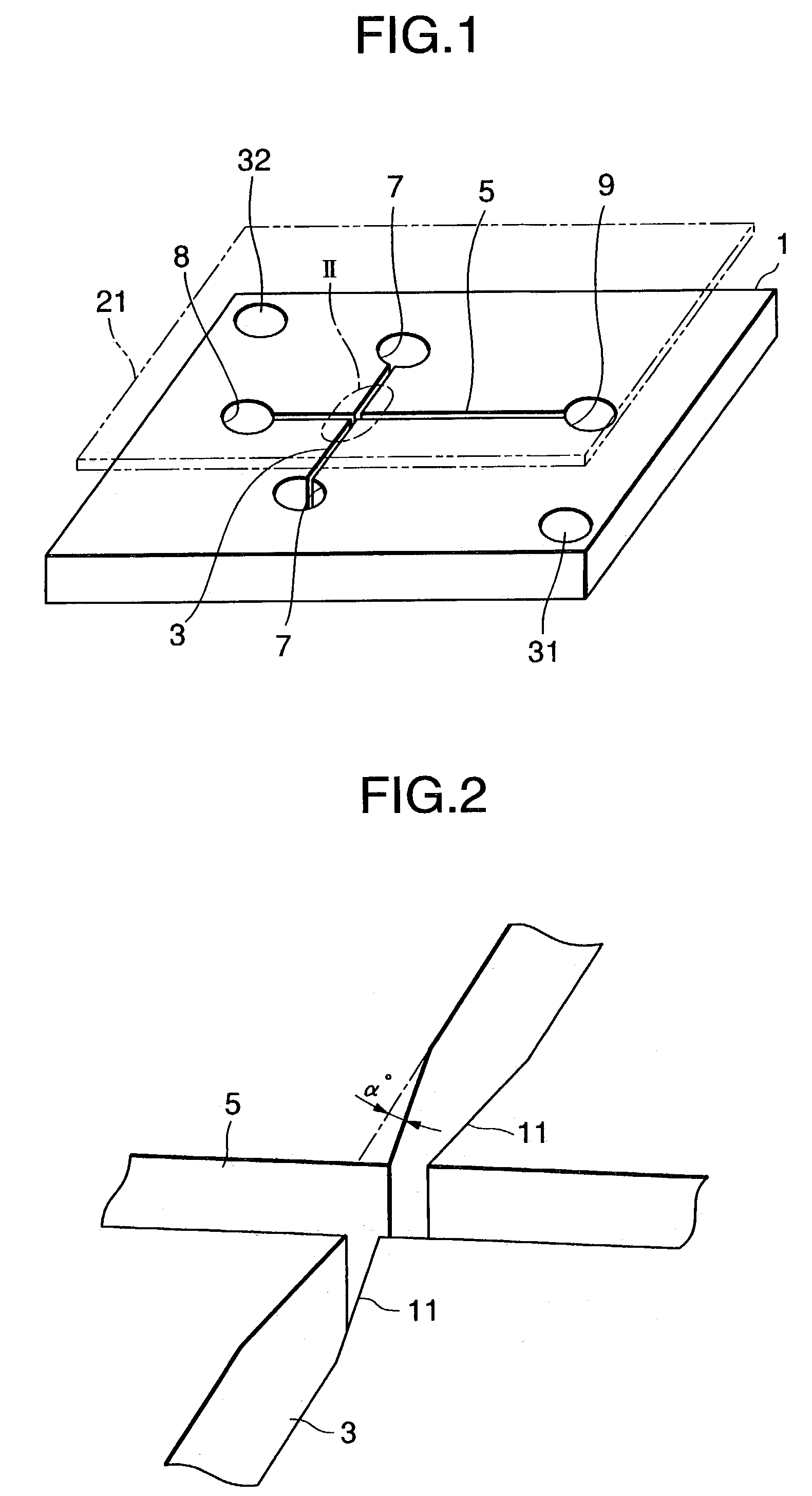
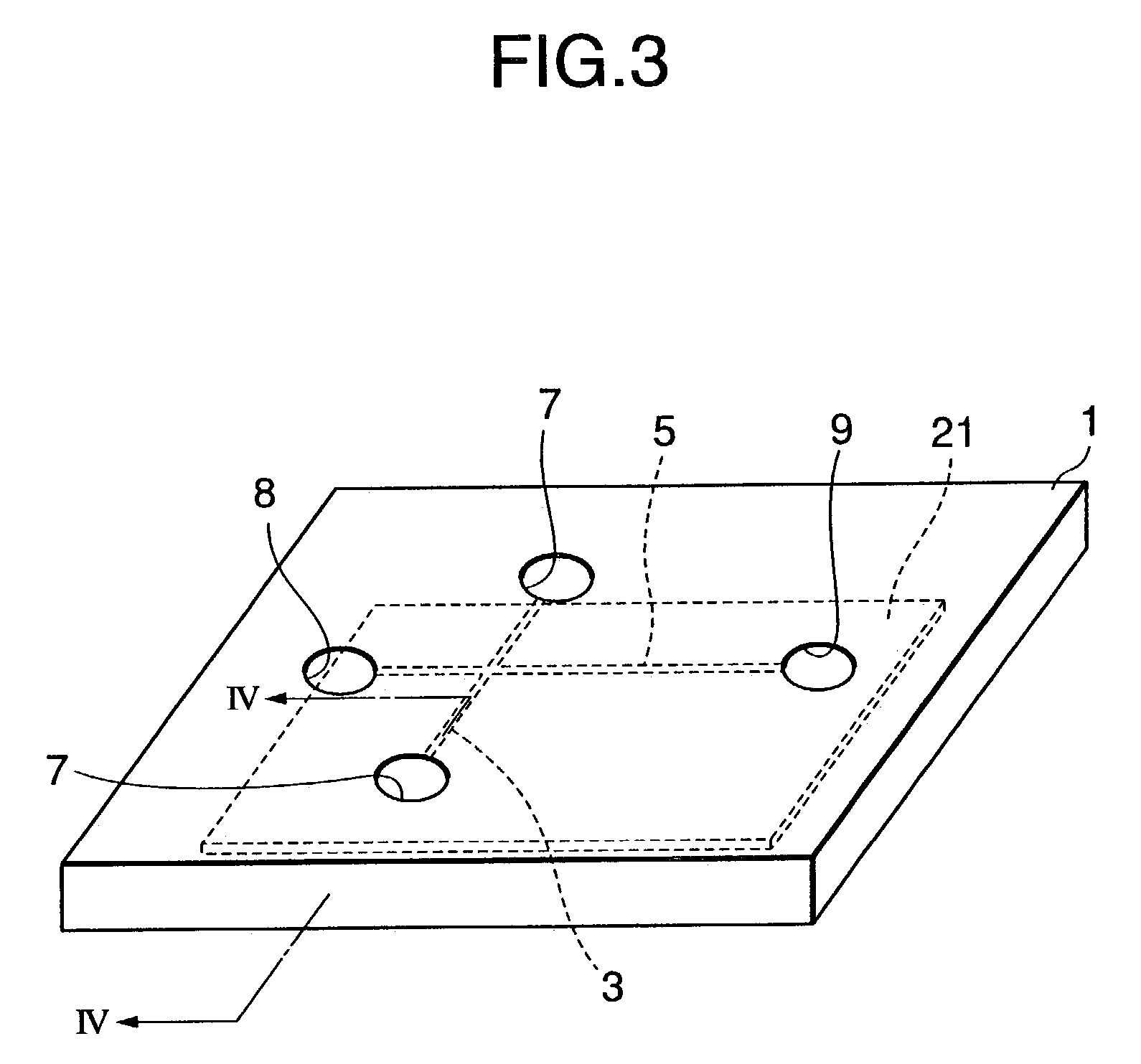
[0088]A first embodiment of the present invention will now be described with reference to FIGS. 1 through 5. FIG. 1 is a perspective view showing a structure of a platy member 1 used for a biochip according to the first embodiment. The platy member 1 comprises a slot-shape of sample introductory passage 3 and also a slot-shape of sample separation passage 5, crossing to each other in a perpendicular direction. There are penetrating injection holes 7, 7 respectively provided at the both ends of the sample introductory passage 3. There is also a penetrating injection hole 8 and a penetrating discharge hole 9, respectively provided at the both ends of the sample separation passage 5.

[0089]The platy member 1 is made of transparent or semi-transparent material, so that the optical detection by UV absorption or fluorescence measurement can be carried out. The platy member is preferably made of synthetic resin, because of their good electric insulation property, reproducibility, and produc...

second embodiment

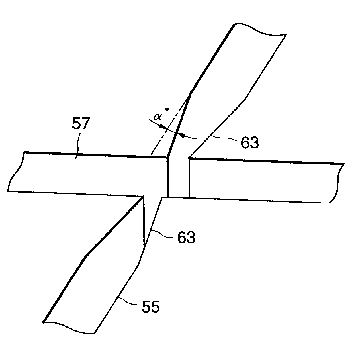
[0118]A second embodiment of the present invention will now be described with reference to FIGS. 6 through 8. There is a platy member 51 as illustrated in FIG. 6. The platy member 51 is made of e.g. glass or acrylic material, and a thick-film resist 53 is provided on one side of the platy member 51. The thick-film resist 53 is provided with a sample introductory passage 55 and a sample separation passage 57 crossing at an intersection part with each other. Both ends of the sample introductory passage 55 are respectively provided with penetrating injection holes 59, 59, and both ends of the sample separation passage 57 are respectively provided with an penetrating injection hole 60 and a penetrating discharge hole 61.

[0119]As illustrated in FIG. 6, a seal member 62 is fixed on the side of the thick-film resist 53 of the platy member 51 as discussed above. The seal member 62 has, injection holes 64, 64, another unillustrated injection hole, and a discharge hole, corresponding to the p...

third embodiment

[0123]A third embodiment of the present invention will now be described with reference to FIGS. 9 through 12. According to the first and second embodiments, the sample is first supplied to the sample introductory passage, and then the sample is supplied to the sample separation passage. According to the third embodiment, however, there is no sample introductory passage, so that the sample may be supplied to the sample separation passage directly.

[0124]There is a platy member 71 as shown in FIG. 9. The platy member 71 is provided with a sample drop portion 73 and a sample separation passage 75. There is a discharge hole 77 provided at one end of the sample separation passage 75. As illustrated in FIG. 10, there is an electrophoretic electrode 79, provided at the sample drop portion 73 of the platy member 71, and electrically connected to an electric circuit 81 elongating to the outside of the sample drop portion 73. Similarly, there is an electrophoretic electrode 83 and an electric ...


PUM

PropertyMeasurementUnit
sizeaaaaaaaaaa
voltageaaaaaaaaaa
widthaaaaaaaaaa

Abstract

To provide a biochip, a biochip manufacturing method, an electrophoresis method, and an electrophoresis apparatus, by which the detection accuracy may improve, there is a biochip introducing a sample in band form into a sample separation passage, by a means for reducing the band width of sample, at which the sample is before being introduced in the sample separation passage in band form. The band of sample supplied to the sample separation passage is compressed, and the expansion by diffusion may be prevented, thus the detection accuracy may improve.

Description

BACKGROUND OF THE INVENTION[0001]1. Field of the Invention[0002]The present invention relates to a biochip, for example, a biochip in which taper sections are provided, as a means for reducing the width of band, at a sample introductory passage for introducing a sample, in order to improve the detection accuracy. Further, the present invention relates to a biochip having a simple structure so that the sample may be directly supplied into a sample separation passage without requiring the sample introductory passage. The present invention also relates to a method of manufacturing the biochip discussed as above, and relates to an electrophoresis method and an electrophoresis apparatus using such biochip.[0003]2. Description of the Related Art[0004]There has been provided a so-called “electrophoresis method” as a method of separating the electric charge nature matter from protein or nucleic acid. In particular, there is a known method of “capillary electrophoresis method” by using micro...

Claims


Application Information

Patent Timeline
Patent Type & Authority Patents(United States)
IPC IPC(8): G01N27/447B29C33/40B29C45/00G01N27/453G01N37/00
CPCG01N27/44743G01N27/44791
Inventor OKAMOTO, NAOMICHIOKUMIYA, NORIYUKISUGIMURA, RYO
Owner PRESIDENT OF SHIZUOKA UNIVERSITY
Why Eureka
Try Eureka