Spiral electrical connection device and slide-type electronic device

a technology of spiral electrical connection and electronic device, which is applied in the direction of insulated conductors, cables, conductors, etc., can solve the problems of not meeting the requirements of being light, thin, short, and small for electronic devices, and the cable or flat cable can easily interfere with other components in the same space, so as to increase the accommodating space the operating space may not need to be increased, and the width of the electrical connection member.

Inactive Publication Date: 2010-07-08
ASUSTEK COMPUTER INC
View PDF10 Cites 8 Cited by
  • Summary
  • Abstract
  • Description
  • Claims
  • Application Information

AI Technical Summary

Benefits of technology

[0010]Additionally, when the cover and the base need more connection points therebetween to be electrically connected, the width of the electrical connection member needs to be increased to dispose more wires. However, since the electrical connection member has an overlapping and windin

Problems solved by technology

Although the long cable (or flat cable) can ensure the electrical connection between the parts, it needs enough accommodating space.
Thus, requirement of being light, thin,

Method used


Image

  • Spiral electrical connection device and slide-type electronic device
  • Spiral electrical connection device and slide-type electronic device
  • Spiral electrical connection device and slide-type electronic device

Examples


first embodiment

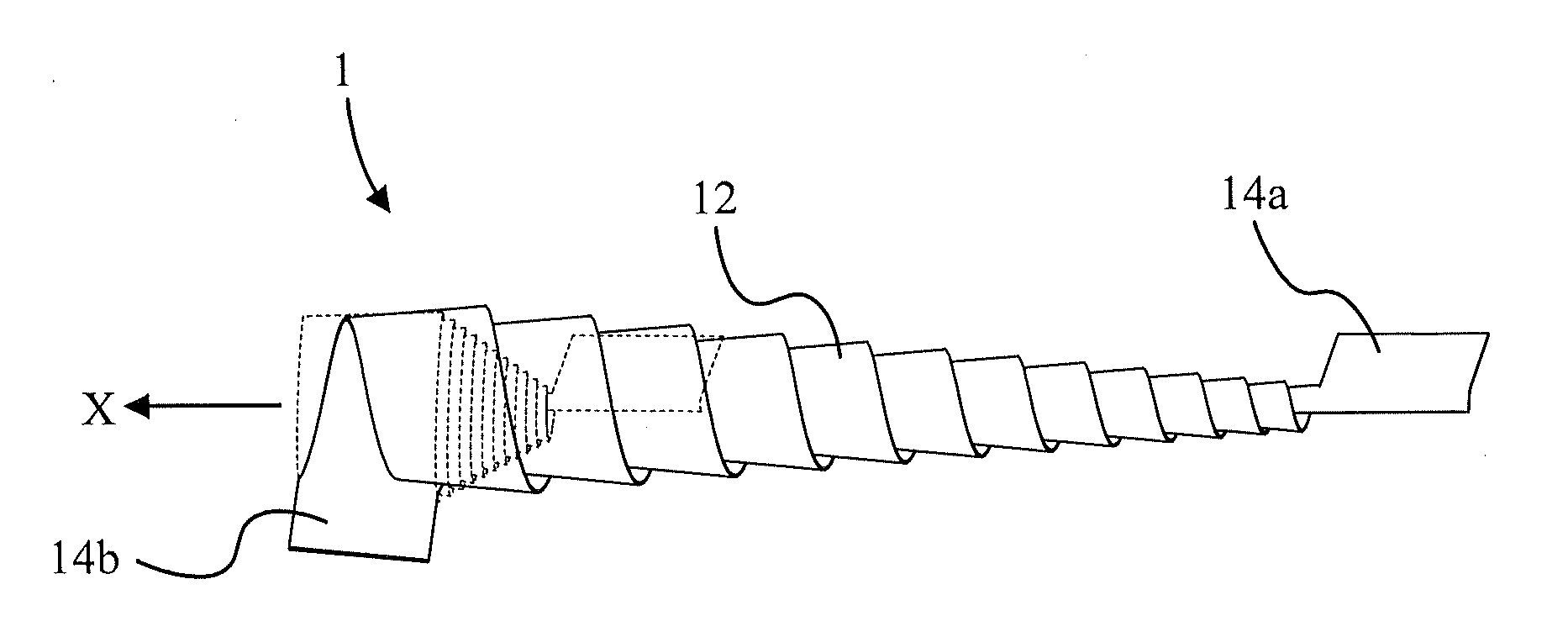
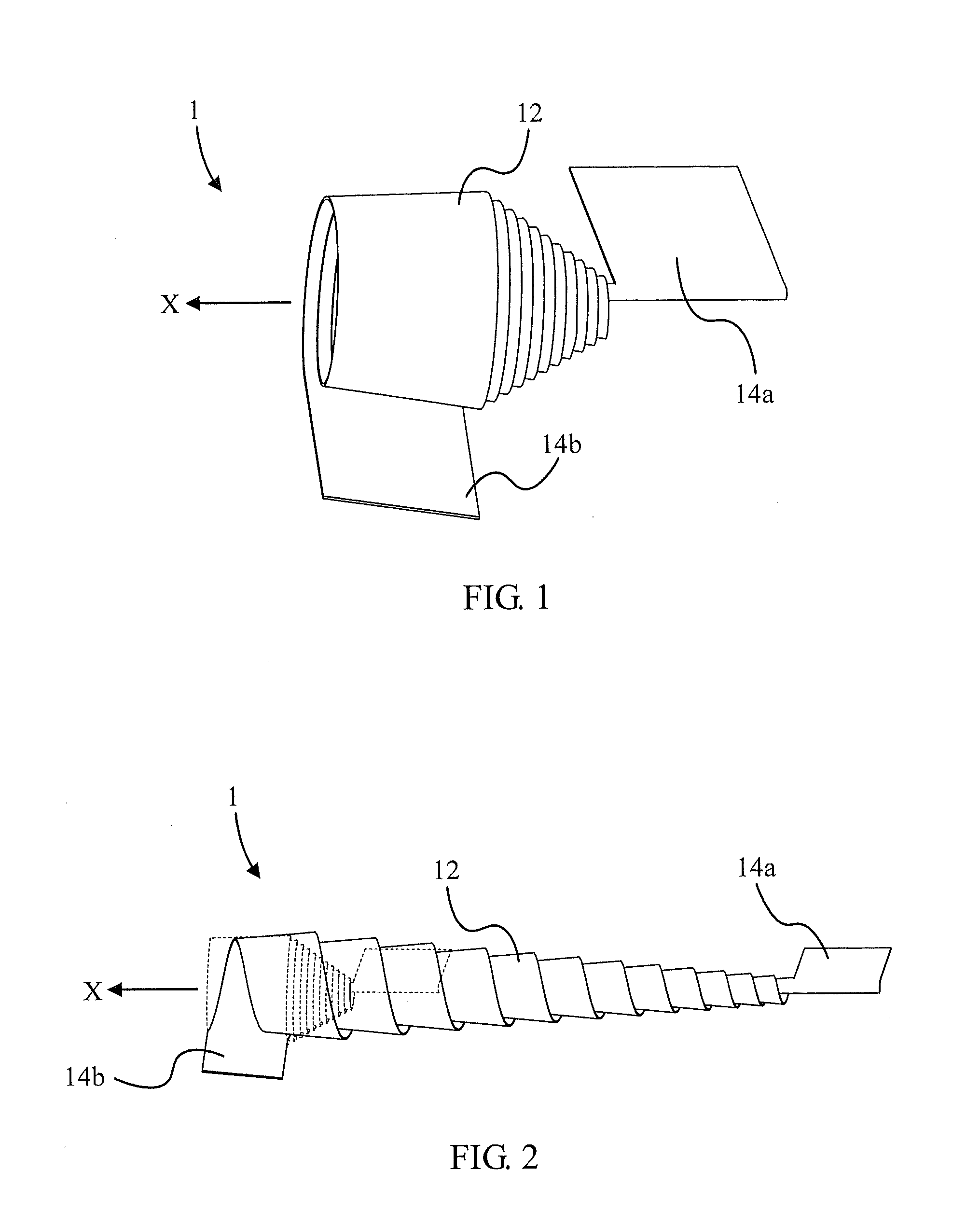
[0028]FIG. 1 is a schematic diagram showing a spiral electrical connection device 1 in a winding state according to the invention. FIG. 2 is a schematic diagram showing the spiral electrical connection device 1 in FIG. 1 in an extending state. Broken lines in FIG. 2 represent the spiral electrical connection device 1 in the winding state. The spiral electrical connection device 1 includes an electrical connection member 12 and two connecting portions 14a and 14b. The two connecting portions 14a and 14b are at a first end and a second end of the electrical connection member 12, respectively. The first end and the second end of the electrical connection member 12 are two sides of the electrical connection member 12, respectively. The electrical connection member 12 may be a plate-shaped electrical connection member. The electrical connection member 12 is overlappingly wound around a winding direction X. When the connecting portions 14a and 14b move along the winding direction X, the e...

second embodiment

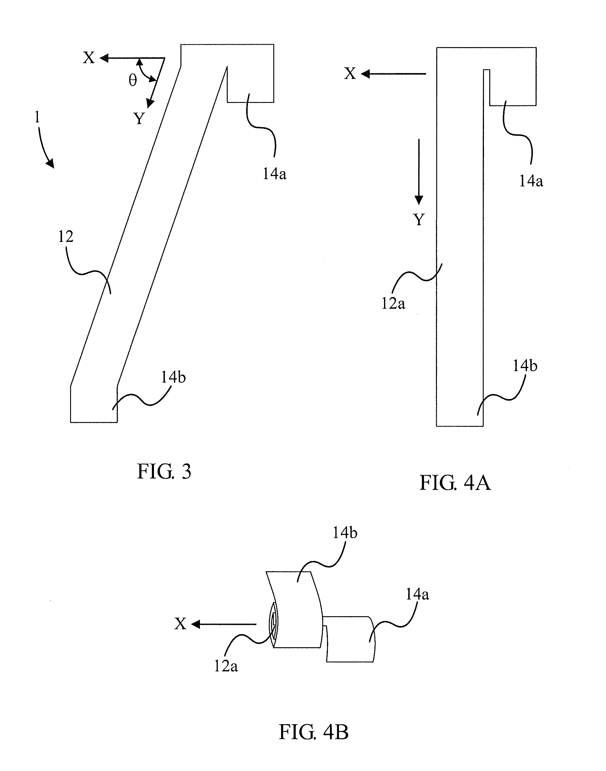
[0030]FIG. 4A is a schematic diagram showing a spiral electrical connection device in the unwinding state according to the invention. FIG. 4B is a schematic diagram showing the spiral electrical connection device in FIG. 4A in the winding state. Unlike the electrical connection member 12 in FIG. 3, in this embodiment, as shown in FIG. 4A, the extending direction Y of the body of the electrical connection member 12a is perpendicular to the winding direction X. Furthermore, the wound electrical connection member 12a includes the winding portions arranged in concentric circles, and the each two consecutive winding portions are series-connected in an approximately superposing mode as shown in FIG. 1.

third embodiment

[0031]FIG. 5A is a schematic diagram showing a spiral electrical connection device in the unwinding state according to the invention. FIG. 5B is a schematic diagram showing the spiral electrical connection device in FIG. 5A in the winding state. FIG. 5C is a schematic diagram showing the spiral electrical connection device in FIG. 5A in the extending state. In practical design, the electrical connection member can be designed to be trapezoid-shaped. As shown in FIG. 5A, an electrical connection member 12b is trapezoid-shaped. As shown in FIG. 5C, a long side portion 122 of the trapezoid-shaped electrical connection member 12b is wound outside, and a short side portion 124 of the electrical connection member 12b is wound inside. The long side portion 122 and the short side portion 124 are represented in the FIG. 5A to FIG. 5C via bold broken lines. Thus, as shown in FIG. 5C, when the electrical connection member 12b extends, the winding portions of the electrical connection member 12...


PUM


Abstract

The invention discloses a spiral electrical connection device and a slide-type electronic device therewith. The slide-type electronic device includes a base, a cover, and the spiral electrical connection device. The cover is slidably connected to the base. The spiral electrical connection device includes an electrical connection member having a first end and a second end and two connecting portions. The two connecting portions are connected to the first end and the second end of the electrical connection member, respectively. The connecting portions are electrically connected to each other via the electrical connection member, and they are connected to the cover and the base, respectively. The electrical connection member winds around a winding direction to the first end. When the cover moves away from the base, the electrical connection member extends. When the cover moves toward the base, the electrical connection member gathers around.

Description

BACKGROUND OF THE INVENTION[0001]1. Field of the Invention[0002]The invention relates to a spiral electrical connection device and a slide-type electronic device therewith and, more particularly, to a spiral electrical connection device with high extensibility and a slide-type electronic device therewith.[0003]2. Description of the Related Art[0004]A common slide-type phone is taken as an example, and it has two parts sliding relative to each other. Most electrical connections between the two parts are directly connected via a cable or a flat cable. The length of the cable or the flat cable is far longer than the length of the two parts after the two parts slides relative to each other to ensure that the electrical connection can be still kept when the two parts move relative to each other. Although the long cable (or flat cable) can ensure the electrical connection between the parts, it needs enough accommodating space. Thus, requirement of being light, thin, short, and small for t...

Claims


Application Information

Patent Timeline
IPC IPC(8): H01B7/06
CPCH04M1/0237H05K1/028H05K2201/051
Inventor LU, HSIN-ILAI, CHIN-CHUNGCHANG, YI-CHIEH
Owner ASUSTEK COMPUTER INC
Why Eureka
Try Eureka