Check patentability & draft patents in minutes with Patsnap Eureka AI!

Nut with lug flare

a lug flare and nut technology, applied in the direction of threaded fasteners, fastening means, screws, etc., can solve the problems of inconsistent push-out resistance, low push-out resistance, and pilot's ability to easily distort the internal threads of the clinch nuts

Active Publication Date: 2014-11-18
R B & W MFG
View PDF22 Cites 19 Cited by
  • Summary
  • Abstract
  • Description
  • Claims
  • Application Information

AI Technical Summary

Benefits of technology

The design achieves improved push-out and rotational resistance, ensuring secure attachment to thin metal panels without thread distortion, and is cost-effective and easy to produce and use.

Problems solved by technology

While this clinch nut may have a relatively high push-out resistance, the deformation of the central pilot can easily distort the internal threads of the clinch nut.
With relatively thin metal panels, however, very little material is forced into the undercut, resulting in a relatively low push-out resistance.
The deformation of the metal panel required to fill both undercuts, however, is difficult to obtain using conventional forming techniques, resulting in inconsistent push-out resistance.
An additional problem with the above-noted self-clinching fasteners is that they typically do not function well with thin metal panels.

Method used


Image

  • Nut with lug flare
  • Nut with lug flare
  • Nut with lug flare

Examples


Embodiment Construction

[0035]Example embodiments that incorporate one or more aspects of the present invention are described and illustrated in the drawings. These illustrated examples are not intended to be a limitation on the present invention. For example, one or more aspects of the present invention can be utilized in other embodiments and even other types of devices. Moreover, certain terminology is used herein for convenience only and is not to be taken as a limitation on the present invention. Still further, in the drawings, the same reference numerals are employed for designating the same elements.

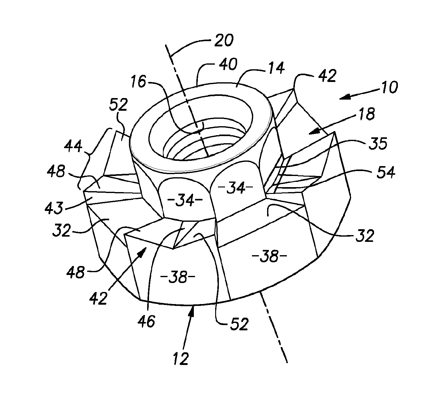
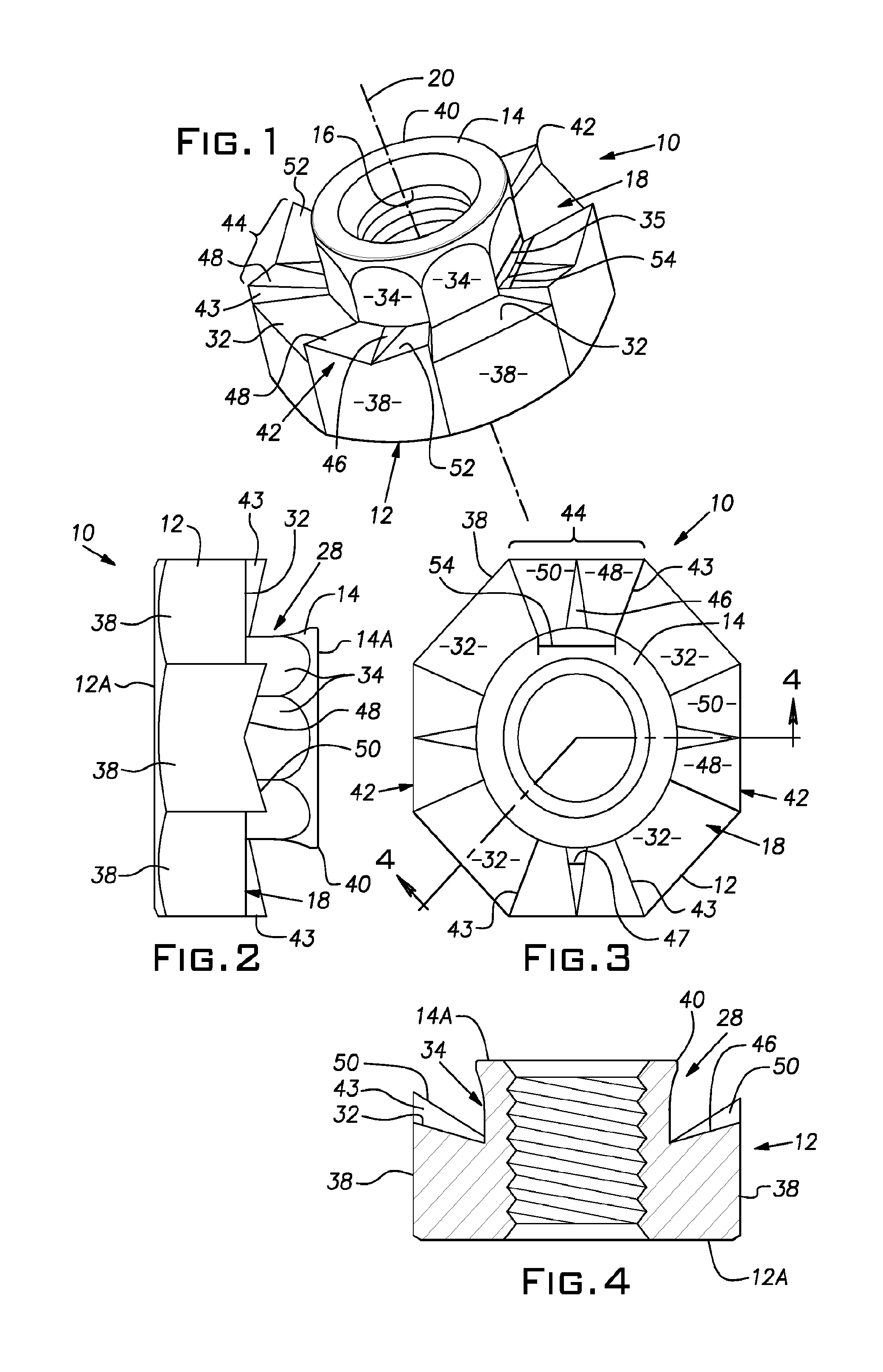
[0036]FIGS. 1-3 illustrate a self-piercing clinch nut 10 or fastener according to a first embodiment of the present invention for attachment to a plastically deformable metal plate or panel. It is noted that while the illustrated embodiment is a nut, other self-clinching fasteners such as, for example, self-clinching studs are within the scope of the present invention. The clinch nut 10 has a body portio...


PUM


Abstract

A clinch nut for attachment to a plastically deformable metal substrate is provided. The clinch nut comprises a body portion with a central axis and a punch portion extending from the body portion and coaxial with the central axis. The body portion includes an annular-shaped surface encircling the central punch portion. The annular-shaped surface includes a plurality of spaced apart lugs encircling the central punch portion. The plurality of lugs each includes a contact surface with a recessed portion where the contact surface engages the metal substrate. A first portion of the contact surface is biased outwards from the central axis upon insertion in the metal substrate to form at least one lug flare during attachment of the nut to the metal substrate. A portion of the metal substrate is entrapped between the at least one lug flare and the body portion.

Description

BACKGROUND OF THE INVENTION[0001]1. Field of the Invention[0002]The present invention generally relates to self-attaching fasteners and, more specifically to clinch nuts.[0003]2. Description of the Related Art[0004]Self-attaching fasteners are used in many industries such as, for example, the automotive and appliance industries to secure various components to metal panels. When clinch nuts are attached to the metal panels, screws or bolts are threaded into the clinch nuts and tightened to prescribed torque values. During installation, the clinch nuts must have sufficient rotational resistance to keep them from rotating relative to the metal panels when the screws are inserted and tightened. During service, the clinch nuts must have sufficient push-out resistance to keep them from pulling out of the metal panel when external forces such as, for example, vibration or other tensile forces are applied.[0005]A clinch nut typically includes a central punch or pilot portion which at least ...

Claims


Application Information

Patent Timeline
Patent Type & Authority Patents(United States)
IPC IPC(8): F16B39/282F16B37/06
CPCF16B37/065F16B39/282F16B37/068F16B33/00F16B37/00F16B35/06
Inventor PAMER, W. RICHARDDENNIS, DOUGLAS P.
Owner R B & W MFG
Features
  • R&D
  • Intellectual Property
  • Life Sciences
  • Materials
  • Tech Scout
  • Unparalleled Data Quality
  • Higher Quality Content
  • 60% Fewer Hallucinations
Learn More