

Freewheeling rotary damping mechanism
a damping mechanism and freewheeling technology, applied in the direction of shock absorbers, aircraft crew accommodation, transportation and packaging, etc., can solve the problems of large space occupation, large volume of overhead storage bins, and damping mechanisms, and achieve the effect of little to no damping
- Summary
- Abstract
- Description
- Claims
- Application Information
AI Technical Summary
Benefits of technology
Problems solved by technology
Method used
Image

Examples
Embodiment Construction
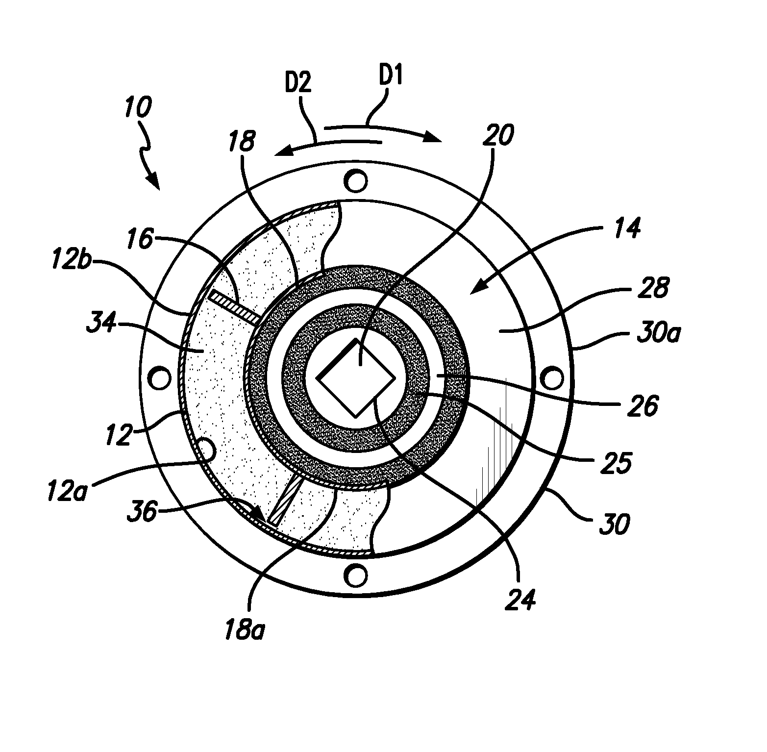
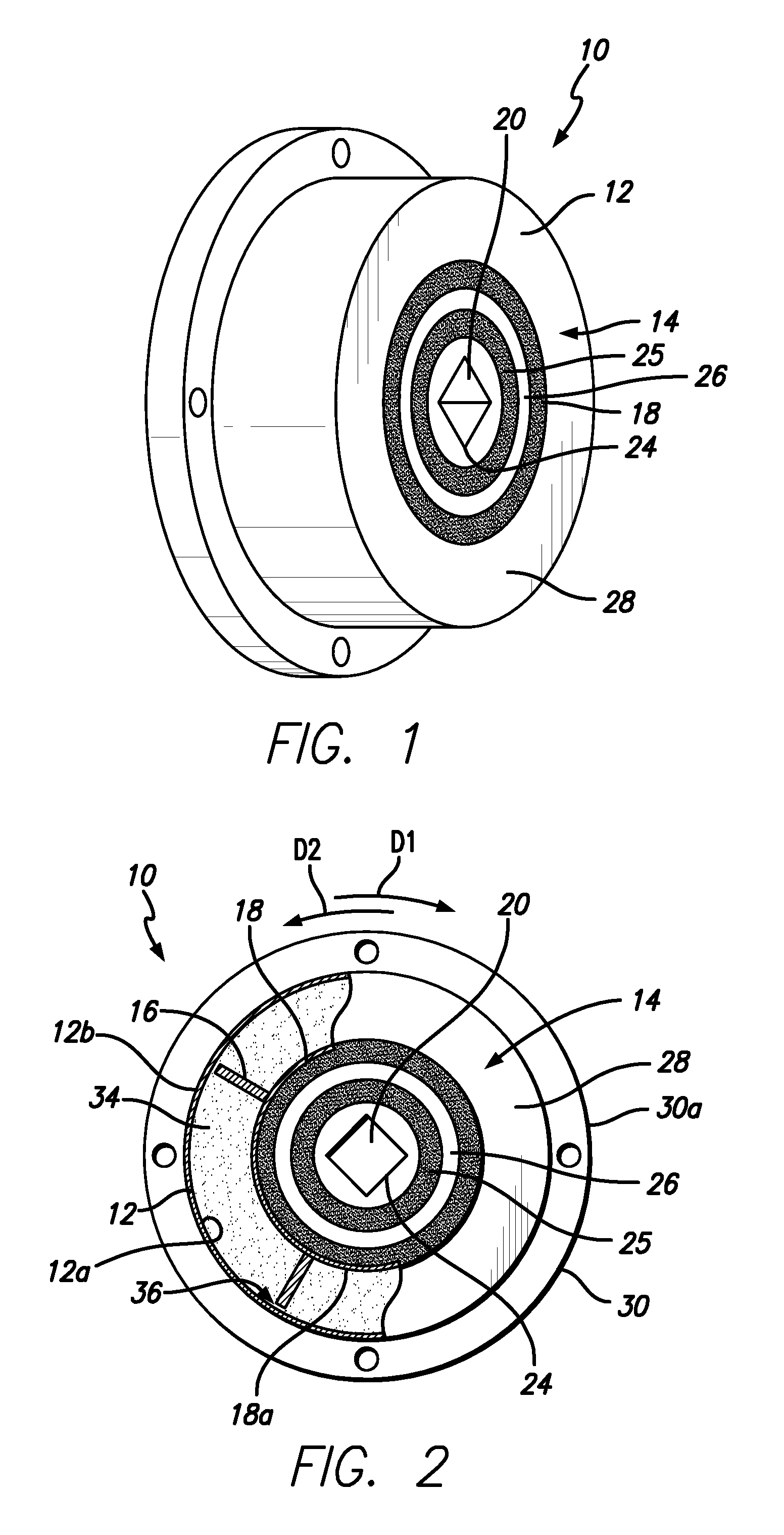
[0004]In accordance with a first aspect of the present invention there is provided a damping mechanism that includes a housing with an inner circumferential surface defined by an assembly outer race, a housing that has an inner circumferential surface and that defines a housing interior, an axle shaft that is rotatable with respect to the housing in a first direction and a second direction and a transmission assembly operatively associated with the axle shaft and disposed at least partially within the housing interior. The transmission assembly includes an assembly intermediate race that has an outer circumferential surface, and a fluid space is defined between the outer circumferential surface of the assembly intermediate race and the inner circumferential surface of the assembly outer race. The damping mechanism also includes a volume of fluid disposed in the fluid space, and at least a first vane disposed between the assembly intermediate race and the inner circumferential surfac...
PUM
 Abstract
Description
Claims
Application Information