Drive for an adjustment device with a worm wheel having a globoid toothing with a cylindrical section

a technology of worm wheel and cylindrical section, which is applied in the direction of gearing, hoisting equipment, chairs, etc., can solve the problems of increasing the fabrication and assembly cost of this type of gear mechanism

Active Publication Date: 2014-12-09
IMS GEAR SE & CO KGAA
View PDF15 Cites 11 Cited by
  • Summary
  • Abstract
  • Description
  • Claims
  • Application Information

AI Technical Summary

Benefits of technology

[0014]In another embodiment, a gear mechanism comprises a drive worm; and the worm wheel configured to engage the drive worm. The second toothing region may axially extend a distance that compensates for axial play, twice axial misalignment and twice expected wear between the individual part...

Problems solved by technology

Due to the need for additional parts, they may increase the...

Method used


Image

  • Drive for an adjustment device with a worm wheel having a globoid toothing with a cylindrical section
  • Drive for an adjustment device with a worm wheel having a globoid toothing with a cylindrical section
  • Drive for an adjustment device with a worm wheel having a globoid toothing with a cylindrical section

Examples


Embodiment Construction

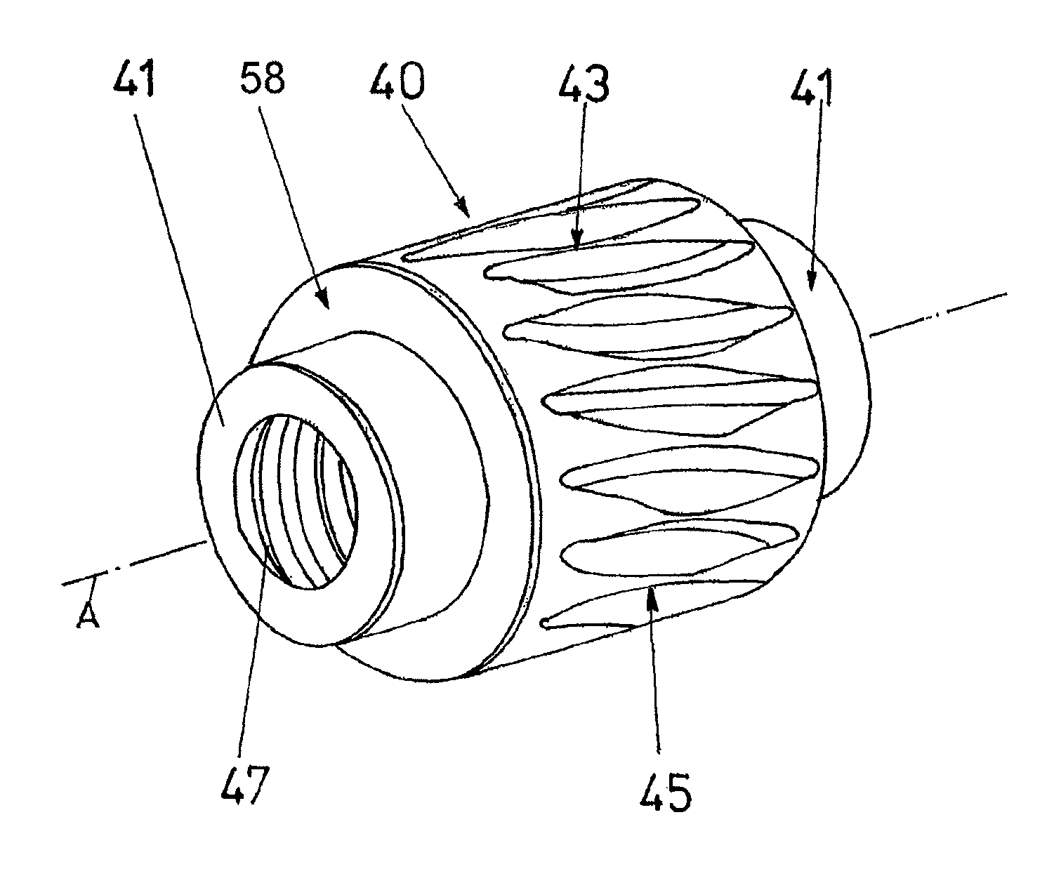
[0026]FIG. 4 is a perspective view illustrating an example of a worm wheel 40. FIG. 5 illustrates a side view of the worm wheel 40 illustrated in FIG. 4. The worm wheel 40 comprises a circumferential section having a second toothing region, for example cylindrical toothing 50, which transitions on both sides into a first toothing region, for example a globoid toothing 52. At least one complete annular surface 58 remains on opposing axial ends of worm wheel 40. An edge region 54 absent of any toothing is positioned adjacent to the annular surface 58 on the axial ends of the worm wheel 40. In the present example, annular projections or flanges 41 project from the opposing annular surfaces 58. The annular surface 58 extend up from the flanges 41 to the outer diameter of worm wheel 40.

[0027]The cylindrical toothing 50 is centered relative to the longitudinal axis of worm wheel 40. The toothing grooves of the cylindrical toothing 50 and the globoid toothing 52 are configured obliquely re...


PUM


Abstract

A worm wheel including first toothing regions transitioning into and on either side of a second toothing region and a complete annular surface on both ends of the worm wheel. The first toothing regions may have a constant outer diameter and the second toothing region may be depressed relative to the first toothing region. The first toothing regions may be globoid toothing regions and the second toothing region may be a cylindrical toothing region.

Description

PRIORITY INFORMATION[0001]This patent application claims priority from German Application No. 10 2004 013 009.4 filed Mar. 16, 2004, which is hereby incorporated by reference.BACKGROUND OF THE INVENTION[0002]The invention relates to a drive for an adjustment device inside a vehicle, and in particular to a drive for an adjustment device with a worm wheel having a globoid toothing with a cylindrical section.[0003]A known drive for seat adjustment devices is described in EP 1 068 093 B1 and illustrated in FIG. 1. A seat of a vehicle (not shown) is fastened to a holding plate 1 which is coupled in turn to a top rail 3. A motor 2 is rigidly connected to the holding plate 1, and thus the top rail 3, with fastening lugs 10. A drive shaft 11 is located on both ends of the motor 2. The drive shaft 11 and a gear mechanism 9 define a connection detailed in EP 1 068 093 B1. The gear mechanism 9 sits within a U-shaped retaining bracket 8, where the retaining bracket 8 may be fastened to the top ...

Claims


Application Information

Patent Timeline
IPC IPC(8): B23F11/00A47C1/023B60N2/22F16H55/22B60N2/44F16H1/16B60N2/02B60N2/06F16M13/00B60N2/90
CPCF16H1/16Y10T74/19953Y10T74/19949Y10T74/19828
Inventor WOEHRLE, MICHAELVOECKT, ANDREAS
Owner IMS GEAR SE & CO KGAA
Why Eureka
Try Eureka