Troffer-style lighting fixture with specular reflector

a technology of specular reflectors and lighting fixtures, which is applied in the direction of lighting support devices, lighting and heating apparatuses, light source combinations, etc., can solve the problems of very energy-inefficient light sources of incandescent lights, relatively inefficient leds, and leds can have a significantly longer operational li

Active Publication Date: 2014-12-09
IDEAL IND LIGHTING LLC
View PDF115 Cites 109 Cited by
  • Summary
  • Abstract
  • Description
  • Claims
  • Application Information

AI Technical Summary

Problems solved by technology

Incandescent lights are very energy-inefficient light sources with approximately ninety percent of the electricity they consume being released as heat rather than light.
Fluorescent light bulbs are more energy efficient than incandescent light bulbs by a factor of about 10, but are still relatively inefficient.
In addition, LEDs can have a significantly longer operational lifetime.
Incandescent light bulbs have relatively short lifetimes, with some having a lifetime in the range of about 750-1000 hours.
Fluorescent bulbs can also have lifetimes longer than incandescent bulbs such as in the range of approximately 10,000-20,000 hours, but provide less desirable color reproduction.
Because of the physical arrangement of the various source elements, multicolor sources often cast shadows with color separation and provide an output with poor color uniformity.
Thus, one challenge associated with multicolor light sources is good spatial color mixing over the entire range of viewing angles.
Uniformity typically improves with an increasing number of bounces, but each bounce has an associated optical loss.
Many of these devices are lossy and, thus, improve the color uniformity at the expense of the optical efficiency of the device.
One design challenge associated with multi-source luminaires is blending the light from LED sources within the luminaire so that the individual sources are not visible to an observer.
However, transmission through such heavily diffusive materials causes significant optical loss.
High power LEDs can draw large currents, generating significant amounts of heat that must be managed.
This can present challenges as plenum space decreases in modern structures.
Furthermore, the temperature in the plenum area is often several degrees warmer than the room environment below the ceiling, making it more difficult for the heat to escape into the plenum ambient.

Method used


Image

  • Troffer-style lighting fixture with specular reflector
  • Troffer-style lighting fixture with specular reflector
  • Troffer-style lighting fixture with specular reflector

Examples


Embodiment Construction

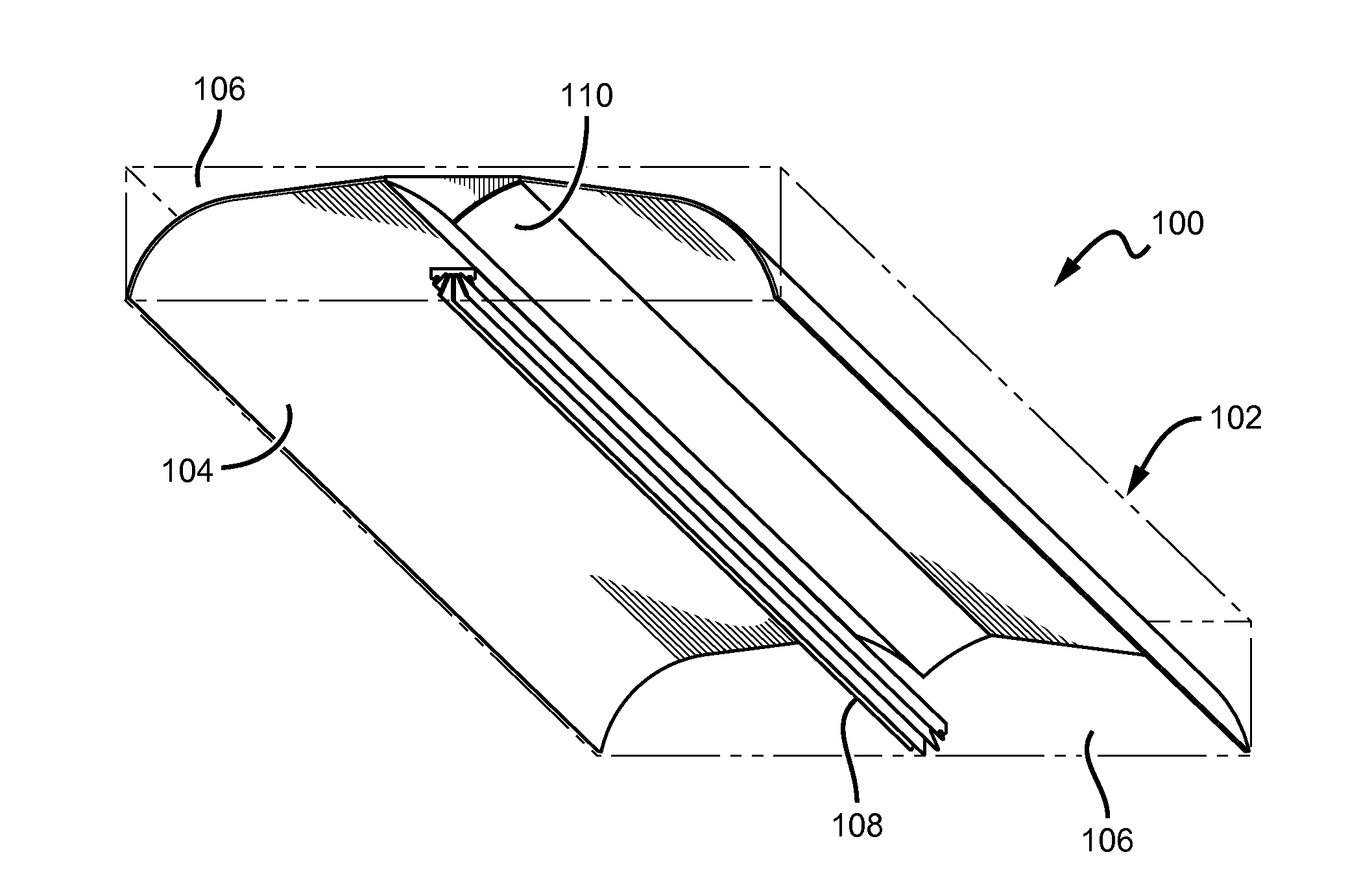
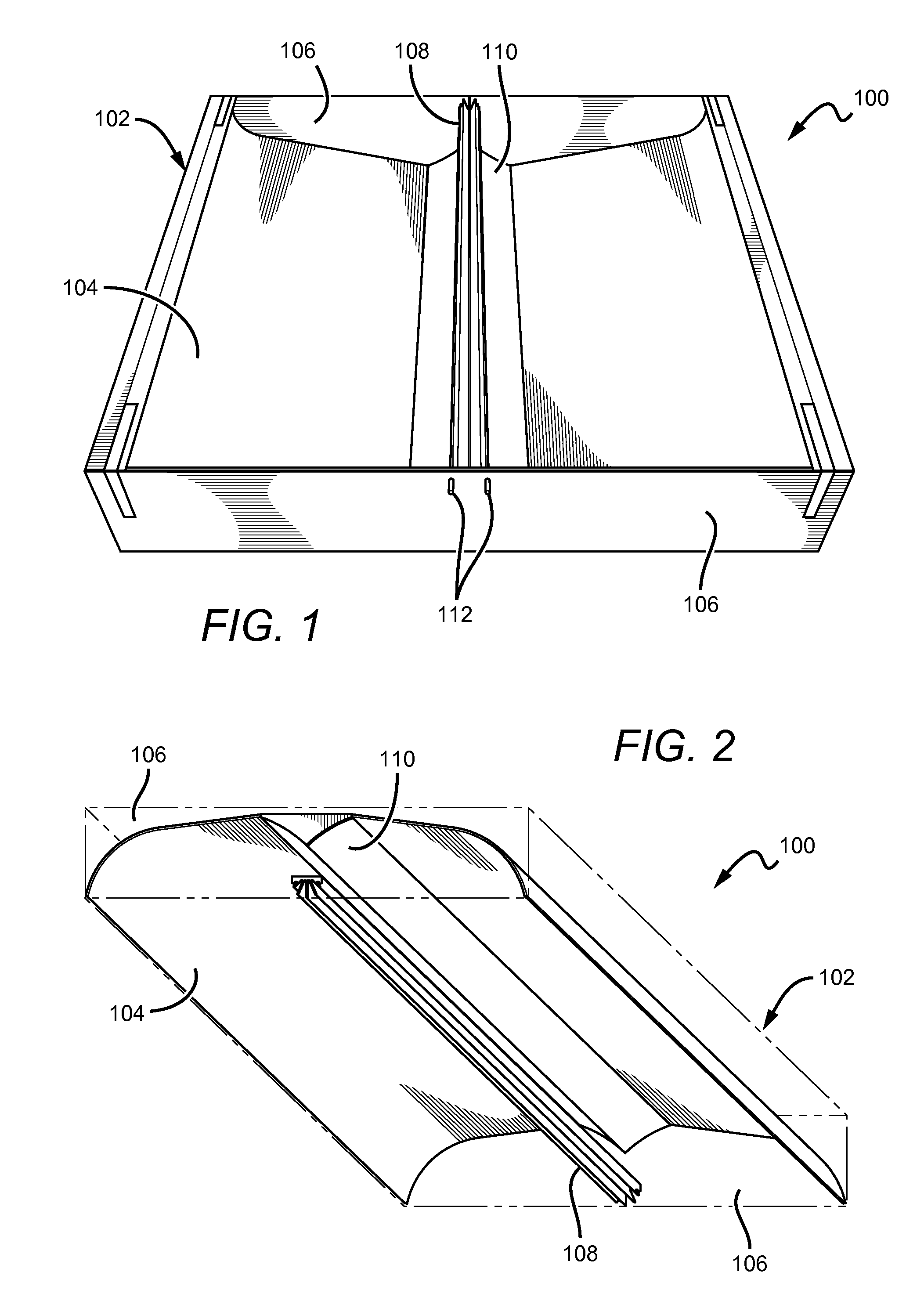
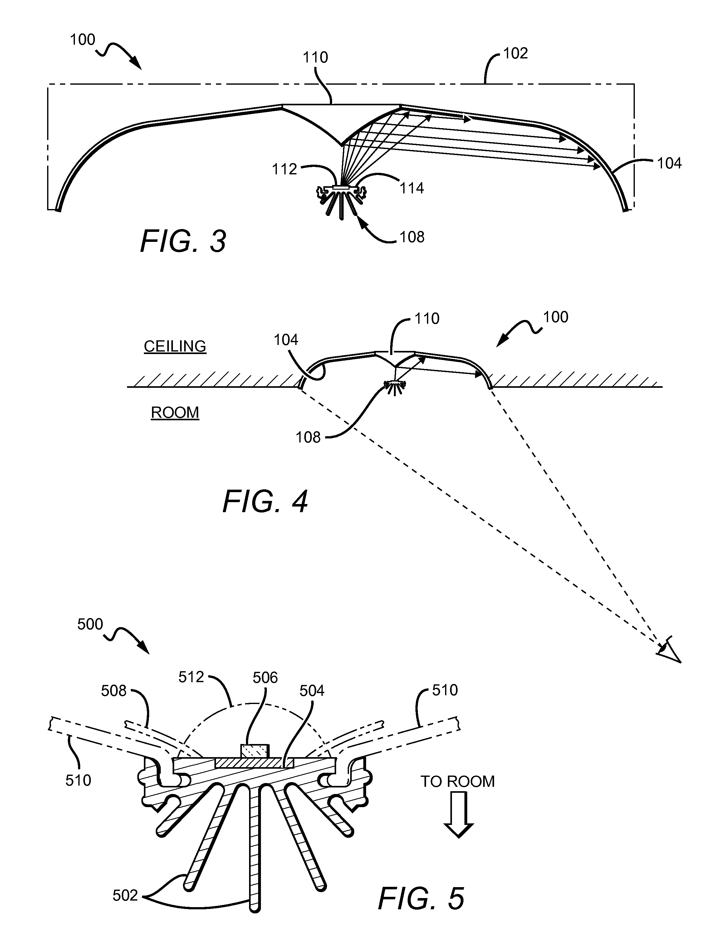
[0032]Embodiments of the present invention provide troffer-style lighting fixture that is particularly well-suited for use with solid state light sources, such as LEDs, for example. An elongated heat sink with a mount surface for light sources runs longitudinally along the spine of the fixture. To facilitate heat dissipation, a portion of the heat sink is exposed to the ambient room environment. An elongated specular reflector also runs along the spine of the device and is disposed proximate to the heat sink. The heat sink and the specular reflector are mounted (e.g., to an end piece) such that a spatial relationship is maintained between the elements. Some of the light from the sources impinges directly on the specular reflector and is redirected towards a back surface. The back surface defines an illuminated surface that receives light directly from the sources and redirected light from the specular reflector. The back surface and the heat sink mechanically obscure any images of t...


PUM

PropertyMeasurementUnit
luminous efficacyaaaaaaaaaa
luminanceaaaaaaaaaa

Abstract

An indirect troffer-style lighting fixture that is particularly well-suited for use with solid state light sources. An elongated heat sink with a mount surface for light sources runs longitudinally along the fixture. To facilitate heat dissipation, a portion of the heat sink is exposed to the ambient room environment. An elongated specular reflector also runs along the device proximate to the heat sink. The heat sink and the specular reflector are mounted such that a spatial relationship is maintained. Some of the light from the sources impinges directly on the specular reflector and is redirected towards a back surface. The back surface defines a luminous surface that receives light directly from the sources and redirected light from the specular reflector. The back surface and the heat sink mechanically obscure any images of the light sources in the specular reflector such that they are not visible in a viewing area.

Description

BACKGROUND OF THE INVENTION[0001]1. Field of the Invention[0002]The invention relates to lighting troffers and, more particularly, to indirect, direct, and direct / indirect lighting troffers that are well-suited for use with solid state lighting sources, such as light emitting diodes (LEDs).[0003]2. Description of the Related Art[0004]Troffer-style fixtures are ubiquitous in commercial office and industrial spaces throughout the world. In many instances these troffers house elongated fluorescent light bulbs that span the length of the troffer. Troffers may be mounted to or suspended from ceilings. Often the troffer may be recessed into the ceiling, with the back side of the troffer protruding into the plenum area above the ceiling. Typically, elements of the troffer on the back side dissipate heat generated by the light source into the plenum where air can be circulated to facilitate the cooling mechanism. U.S. Pat. No. 5,823,663 to Bell, et al. and U.S. Pat. No. 6,210,025 to Schmidt...

Claims


Application Information

Patent Timeline
Patent Type & Authority Patents(United States)
IPC IPC(8): F21V7/20F21V29/00F21V29/505
CPCF21Y2103/003F21Y2101/02F21V7/04F21V13/04F21S8/026F21V25/12F21V7/0008F21S8/04F21S8/061F21V29/2237F21Y2113/005F21V7/0025F21V7/22F21V29/777F21Y2103/10F21Y2115/10F21Y2113/13F21V7/24F21V7/30
Inventor DURKEE, JOHNPICKARD, PAUL KENNETH
Owner IDEAL IND LIGHTING LLC
Why Eureka
Try Eureka