
Drum stand stabilizing assembly

a technology of stabilizing assembly and drum stand, which is applied in the direction of instruments, percussion musical instruments, instruments, etc., to achieve the effects of reducing vibration and movement, facilitating use, and facilitating the use of the instrumen

Active Publication Date: 2015-01-06
HALLERBERG DALE A
View PDF6 Cites 0 Cited by
  • Summary
  • Abstract
  • Description
  • Claims
  • Application Information

AI Technical Summary

Benefits of technology

[0013]Various prior inventions have been disclosed that provide support stands for musical instruments such as percussion instruments, snare, and single-tenor drums, but none of the listed inventions provide the claims of this invention. The ideal invention would provide instrument support that is extremely stable under the use and abuse expected during heavy practice and performance. It would support the drum and maintain the proper orientation so that vibration and movement are eliminated or minimized. It would be of a design that allows very quick mounting and dismounting of the instrument. It would use few parts to simplify the use, reduce lost parts, and cut down on manufacturing costs. It would require no further adjustment or tightening once installed. It would firmly attach to the instrument in an unobtrusive location. It would be robust, yet low in weight. The proposed invention provides these features.
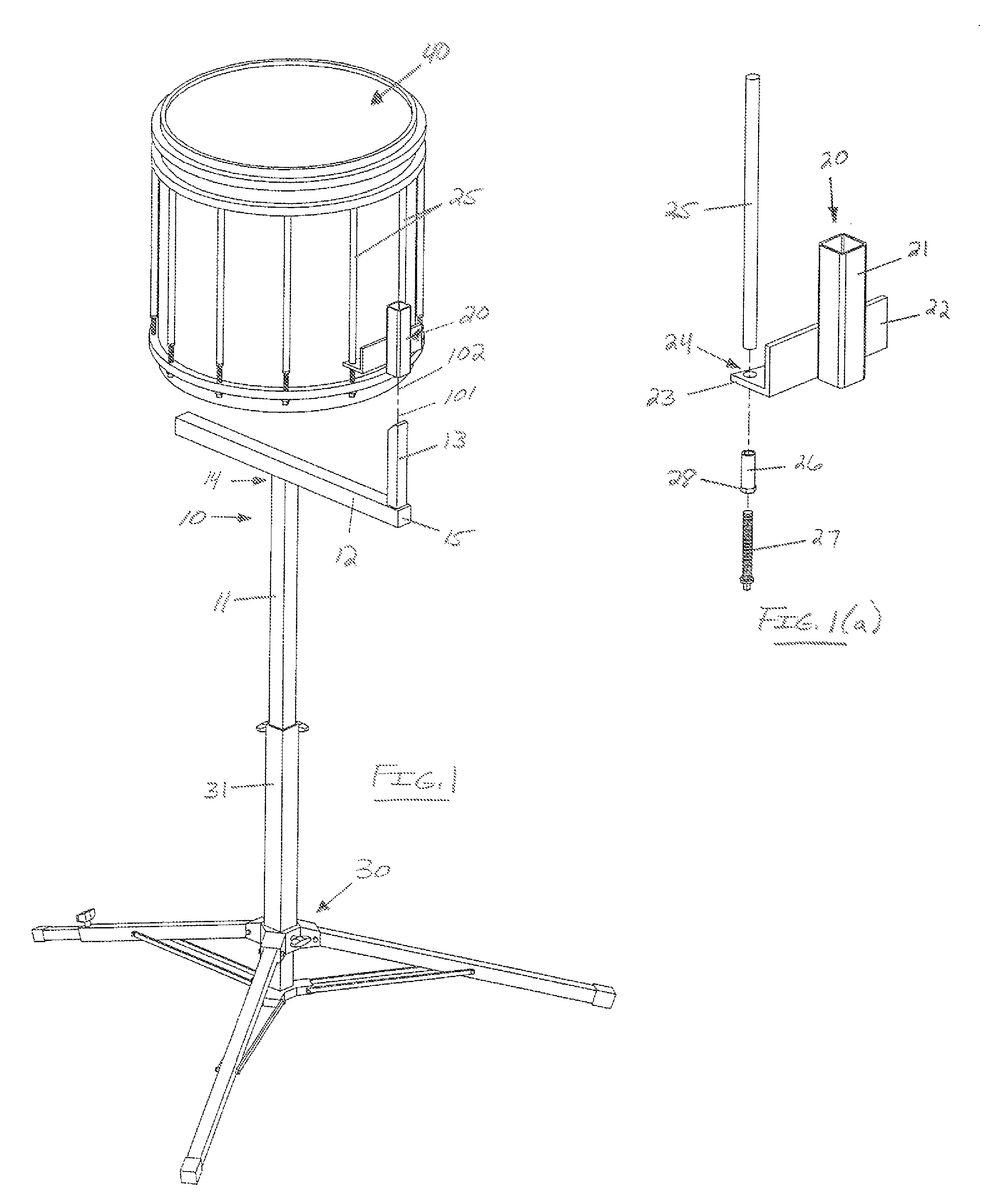
[0014]One of the objects of this invention is to provide instrument support that is extremely stable. The Hoshino '253 Patent, for example, discloses a single post instrument support with one arm which has the tendency to sway, bounce, and vibrate. The current invention improves on this by providing a lateral support which supports the bottom edge of the drum in two places, typically the back of the drum and the front of the drum. These supports are cushioned by resilient material such as hard rubber. The vertical riser underneath this horizontal support is located directly below the center-of-gravity of the drum which provides the optimal location for stability. The receiver is firmly attached to the drum, and the fit between the receiver and the post is snug. These elements of the invention cooperate to provide stability.
[0015]Another object of this invention is to maintain alignment of the instrument in a preferred orientation for practice or performances. This is attained by the mating shape of the post and receiver. In the preferred embodiment this mating shape is square, which provides the benefits of simplicity, low cost, and non-rotation. Other non-round shapes for the post are possible, including rectangular, triangular, “T”-shaped, or two round posts in combination.
[0016]Another object of this invention is to allow very quick mounting and dismounting of the instrument to the stand. This is attained by the post of the invention which is easy to place into the mating receiver that is attached to the drum. By tightly controlling the tolerances of this mating the invention provides for very quick mounting and dismounting of the instrument to the stand.
[0017]Another object of this invention is to reduce the parts needed for the instrument stand. This is attained by the invention needing few adjustable parts or tightening bolts such as wing nuts.

Problems solved by technology

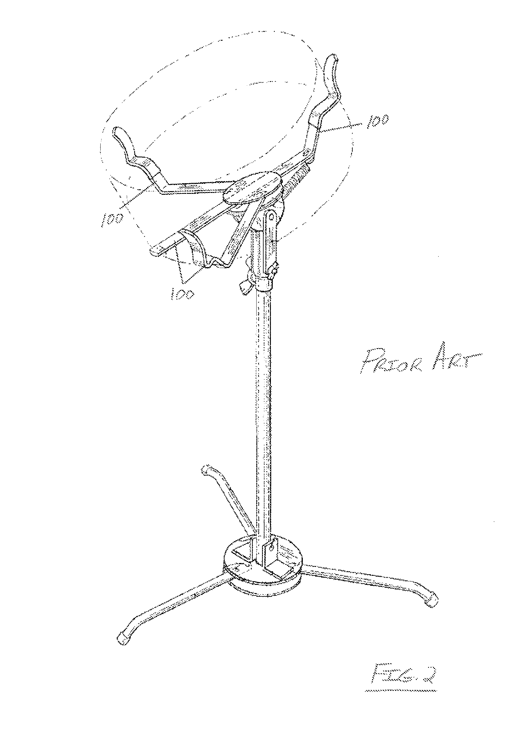
While the above patents and many subsequent patents of the prior art disclose various instrument stands generally, and drum stands particularly, none of the prior art discloses a drum stand utilizing a post which mates to a receiver on the drum together with a lateral support which holds the weight of the instrument in multiple locations to allow for fast, simple, and stable placement of the instrument on the stand.

Method used


Image

  • Drum stand stabilizing assembly
  • Drum stand stabilizing assembly
  • Drum stand stabilizing assembly

Examples


Embodiment Construction

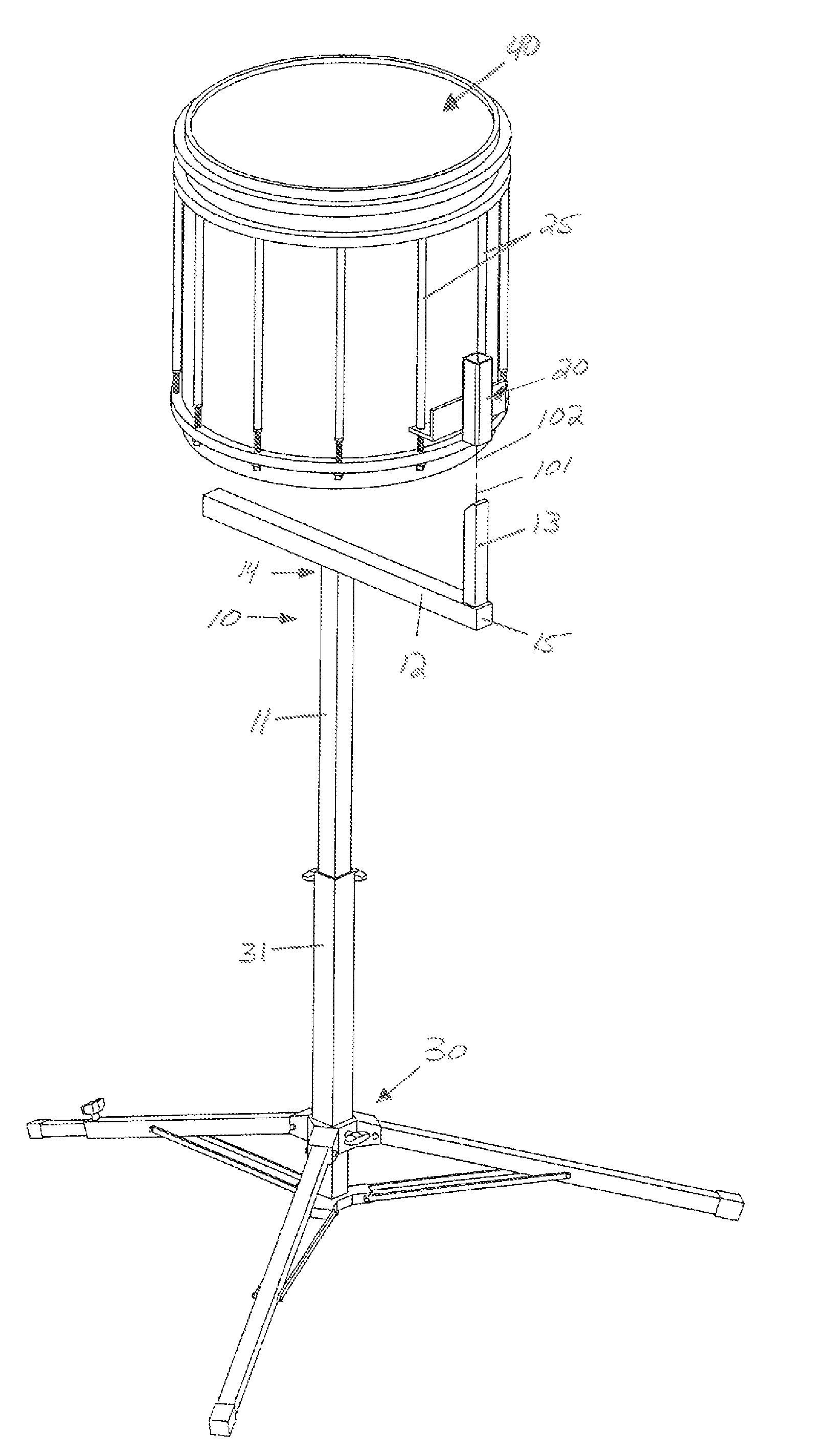
[0074]Referring now the drawings with more specificity, FIG. 1 attempts to depict a preferred drum stand stabilizing assembly according to the present invention with a drum 40 mounted thereto. The drum or percussion instrument stand stabilizing assembly according to the present invention may be said to comprise, in combination, a stand base 30; a support assembly 10; and a drum-to-support receiver unit or interface construction 20.

[0075]Generally referencing FIG. 1, the support assembly 10 is held or supported by the stand base 30. In this regard, the stand base 30 is preferably of a tripod type construction having an upwardly oriented member 31 matable with the riser element 11 of the support assembly 10. The support assembly 10 mates with the preferred drum-to-support receiver unit 20 as well as with alternative receiver units 50, 60, 70, and 80. The receiver unit 20 is preferably attached to the percussion instrument or drum 40 via certain fastening means.

[0076]Referencing FIG. 1...


PUM


Abstract

A drum stand stabilizing assembly, generally intended for marching percussion instruments such as snare drums. The invention uses a lateral support to hold the weight of the instrument in multiple locations, a post or posts to stabilize the instrument in the proper position, and a mating receiver mounted to the instrument to allow for assembly of the complete support structure. The assembly provides for a stable support structure and maintains the instrument in the proper orientation for practice or performance. The assembly provides for fast and simple mounting of the instrument.

Description

PRIOR HISTORY[0001]This non-provisional U.S. Patent Application claims the benefit of U.S. Provisional Patent Application No. 61 / 688,078 filed in the United States Patent and Trademark Office on 8 May 2012, the specifications of which are hereby incorporated by reference thereto.BACKGROUND OF THE INVENTION[0002]1. Field of the Invention[0003]This invention relates to new and useful improvements in support stands for drums and other musical instruments. More particularly, the present invention relates to a support stand which holds a snare drum or single tenor, for example a marching snare drum.[0004]2. Brief Description of the Prior Art[0005]Referencing FIG. 2 of the patent illustrations appended to these specifications, the reader will see that an exemplary prior art stand for musical instruments, especially for percussion instruments, typically shows the use of a tripod type stand with three or more supports which support the bottom edge of the drum in order to hold the drum in a ...

Claims


Application Information

Patent Timeline
Patent Type & Authority Patents(United States)
IPC IPC(8): G10D13/02
CPCG10D13/026G10D13/02G10D13/28
Inventor HALLERBERG, DALE A.
Owner HALLERBERG DALE A
Learn More