Saw blade clamping mechanism for a power tool

a power tool and clamping mechanism technology, applied in the field of power sawing tools, can solve the problems of high manufacturing cost, complicated installation procedure, and broken saw blades, and achieve the effect of quick mounting or dismounting of saw blades

Inactive Publication Date: 2007-05-01
MOBILETRON ELECTRONICS
View PDF10 Cites 17 Cited by
  • Summary
  • Abstract
  • Description
  • Claims
  • Application Information

AI Technical Summary

Benefits of technology

[0006]The present invention has been accomplished under the circumstances in view. It is therefore an object of the present invention to provide a saw blade clamping mechanism for a power sawing tool, which allows quick mounting or dismounting of the saw blade.
[0007]It is another object of the present invention to provide a saw blade clamping mechanism for a power sawing tool, which has a simple structure and is inexpensive to manufacture.

Problems solved by technology

During cutting working, the saw blade may break, and the operator must detach the broken saw blade from the sawing tool for a replacement.
However, because this arrangement uses a number of complicated parts, the installation procedure is complicated, and the manufacturing cost is high.
Further, the complicated parts may fail easily during working of the power tool.

Method used


Image

  • Saw blade clamping mechanism for a power tool
  • Saw blade clamping mechanism for a power tool
  • Saw blade clamping mechanism for a power tool

Examples


Embodiment Construction

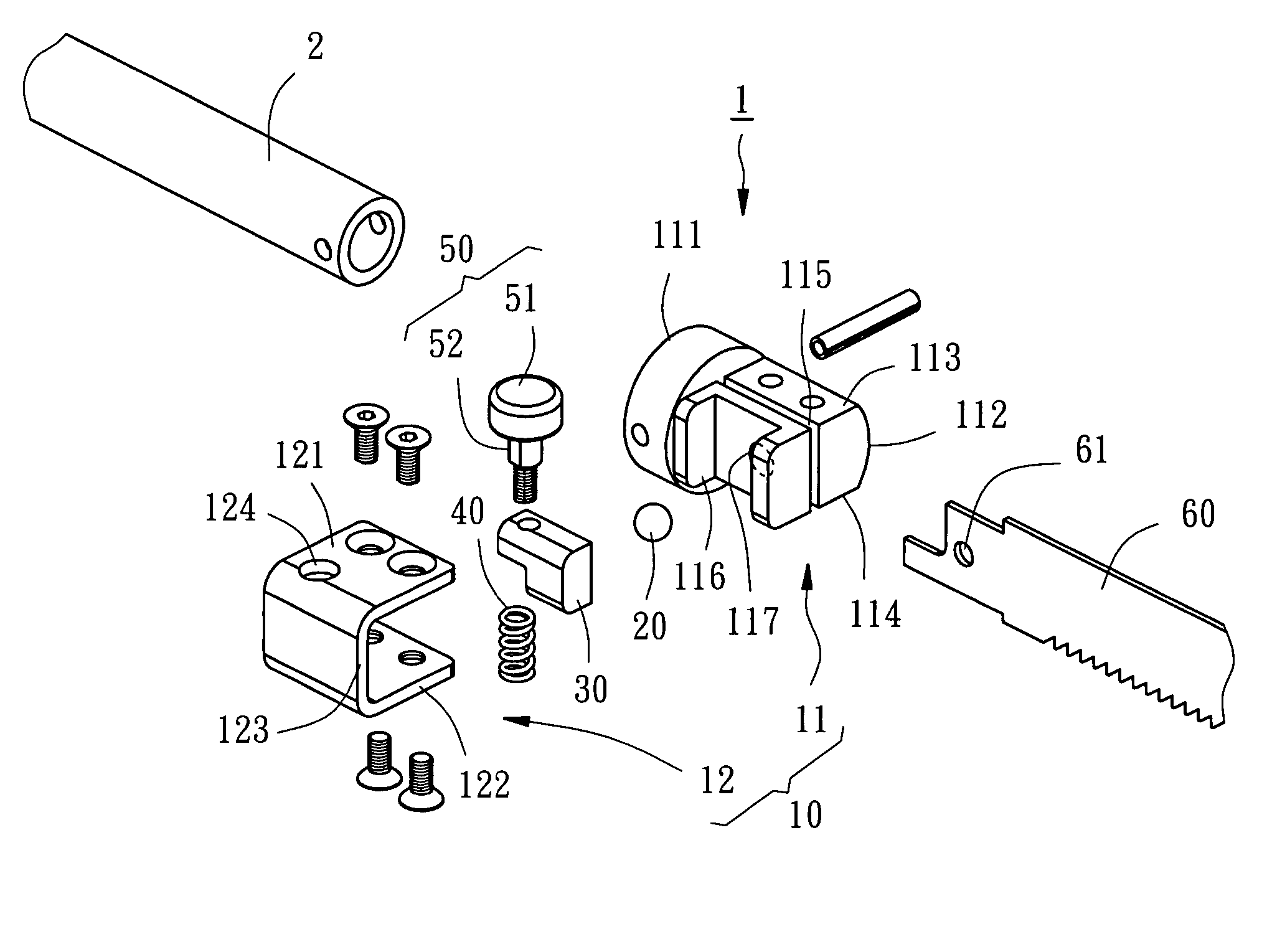
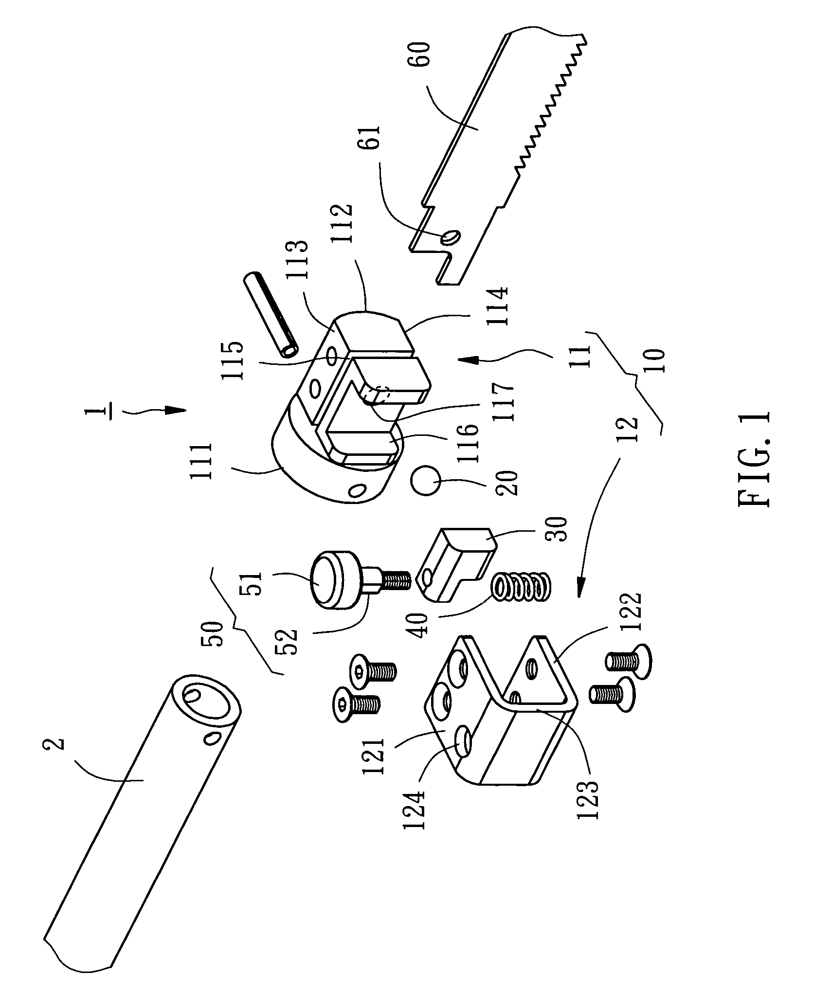
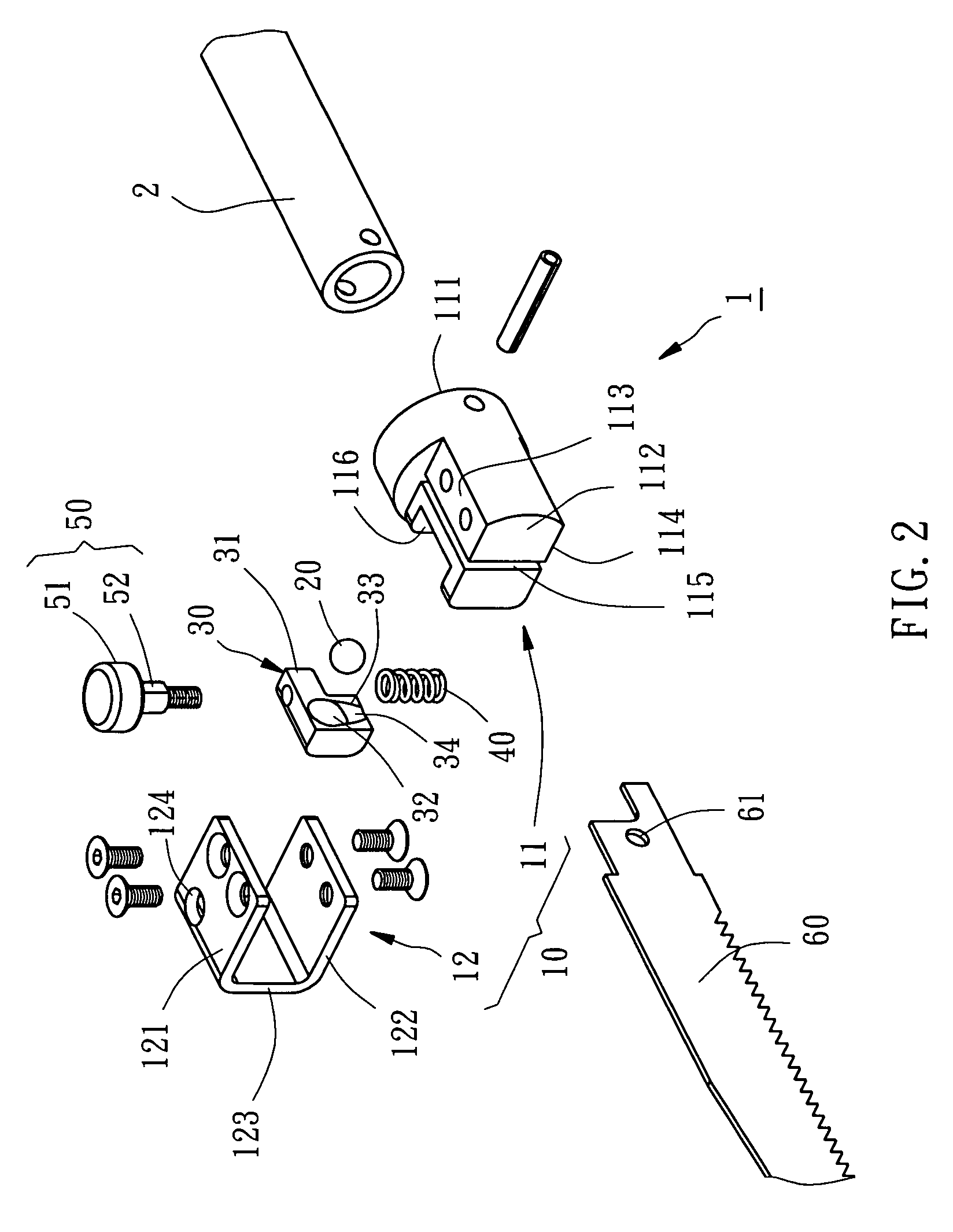
[0017]Referring to FIGS. 1–5, a saw blade clamping mechanism 1 in accordance with a preferred embodiment of the present invention is shown comprising a holder 10, a ball 20, a sliding block 30, a spring member 40, and a control knob 50.

[0018]The holder 10 comprises a holder block 11 and a limiter 12. The holder block 11 is connectable to a drive shaft 2, having a first end 111 for connection to the drive shaft 2, a second end 112, a first lateral side 113, a second lateral side 114 disposed in parallel and opposite to the first lateral side 113, a receiving slot 115, which extends from the second end 112 toward the first end 111 in a predetermined length and cuts through the first lateral side 113 and the second lateral side 114, i.e. the receiving slot 115 has three openings disposed respectively at the first and second lateral sides 113, 114 and the second end 112, a sliding way 116 cut through the first lateral side 113 and the second lateral side 114 at one side, and a through h...


PUM

PropertyMeasurementUnit
diameteraaaaaaaaaa
lengthaaaaaaaaaa
forceaaaaaaaaaa

Abstract

A saw blade clamping mechanism includes a holder connectable to a reciprocating shaft of a power sawing tool. The holder has a sliding way, a receiving slot for insertion of a saw blade, and a through hole in communication between the sliding way and the receiving slot. A steel ball is movably installed in the through hole. A sliding block is mounted in the sliding way and moveable between a first position for receiving the steel ball for removal of the saw blade out of the receiving slot and a second position to force the steel ball into the receiving slot to lock the saw blade. A spring member supports the sliding block in the second position. A control knob is connected to the sliding block for operation by the user to move the sliding block from the second position to the first position.

Description

BACKGROUND OF THE INVENTION[0001]1. Field of the Invention[0002]The present invention relates to a power sawing tool having a reciprocating shaft connected to a saw blade, and more specifically to a saw blade clamping mechanism for the power sawing tool.[0003]2. Description of the Related Art[0004]The saw blade clamping mechanism, which is so-called saw blade connector, for a sawing tool is adapted to secure a saw blade to a reciprocating shaft for allowing the saw blade to be reciprocated by the reciprocating shaft. During cutting working, the saw blade may break, and the operator must detach the broken saw blade from the sawing tool for a replacement. Therefore, it is important to design a saw blade clamping mechanism, which allows quick replacement of the saw blade.[0005]U.S. Pat. No. 6,009,627 discloses a saw blade clamping arrangement for a power tool. According to this design, the saw blade clamping arrangement comprises a biasing member interconnected with the drive shaft and...

Claims


Application Information

Patent Timeline
Patent Type & Authority Patents(United States)
IPC IPC(8): B27B11/06B27B21/02
CPCB23D51/10Y10T83/9481Y10T83/7697
Inventor GUO, DUNG-CHIN
Owner MOBILETRON ELECTRONICS
Why Eureka
Try Eureka