
Window blind carrier slide

a window blind and carrier technology, applied in the field of window blind carrier slide, can solve the problems of user inconvenience and danger, disadvantageous increase of material and manufacturing costs of curtains, user inconvenient disassembly, etc., and achieve the effect of convenient mounting and disassembly, and quick mounting and disassembly of window blinds

Inactive Publication Date: 2007-06-21
PAPER FABRIC ENTERPRISES
View PDF20 Cites 4 Cited by
  • Summary
  • Abstract
  • Description
  • Claims
  • Application Information

AI Technical Summary

Benefits of technology

[0005] A primary object of the present invention is to provide a window blind carrier slide that includes two detachably connectable parts to enable a user to conveniently mount and dismount a window blind by engaging or disengaging the first part with or from the second part in a direction normal to a front side of the first part.
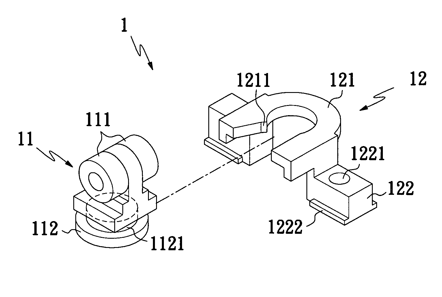
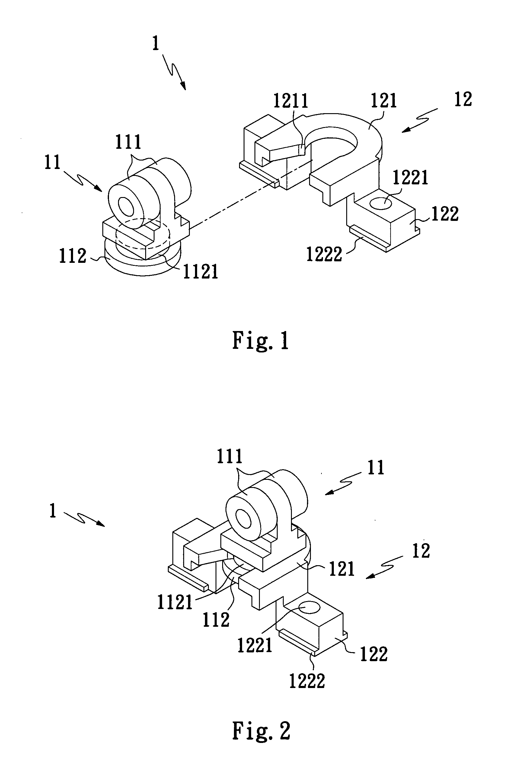
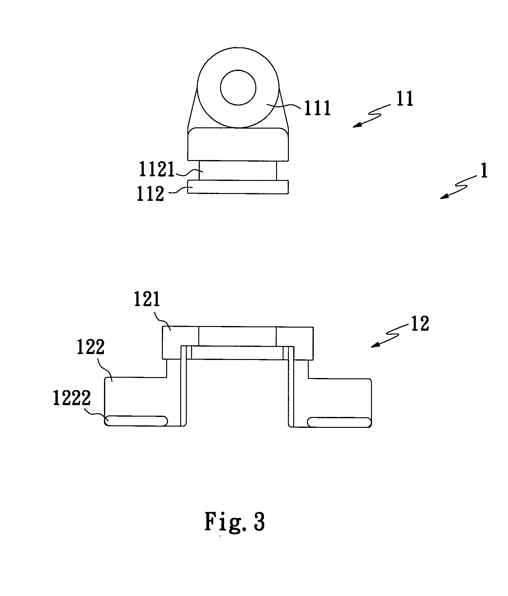
[0006] To achieve the above and other objects, the window blind carrier slide according to the present invention includes a sliding body having at least one set of f fixing members located at an upper front side and an upper rear side thereof for slidably mounting in a guide channel of an upper rail for a window blind, and at least one linking seat located at a lower side thereof; and a linking block having at least one engaging portion provided at an upper side thereof for tightly engaging with the at least one linking seat on the sliding body, and two mounting legs located at two lower lateral sides of the at least one engaging portion for locking to a guide channel in a lower rail for the window blind. The linking block is detachably connected to the sliding body through engagement of the at least one engaging portion on the linking block with the at least one linking seat of the sliding body from a front side of the linking seat, enabling quick mounting and dismounting of the window blind.

Problems solved by technology

This is very inconvenient and dangerous for the user to do so.
The stoppers disadvantageously increase the material and manufacturing costs of the curtain.
The user has to inconveniently dismount the whole upper guide rail from the window remove the fixing rod and the curtain fabrics from the guide channel.

Method used


Image

  • Window blind carrier slide
  • Window blind carrier slide
  • Window blind carrier slide

Examples


Embodiment Construction

[0017] Please refer to FIGS. 1, 2, and 3 that are exploded perspective, assembled perspective, and exploded front views, respectively, of a window blind carrier slide 1 according to a first embodiment of the present invention. As shown, the window blind carrier slide 1 includes a sliding body 11 and a linking block 12. The sliding body 11 includes two fixing members 111 separately located at upper front and upper rear sides of the sliding body 11 for slidably mounting to a guide channel 81 in an upper rail for a window blind (see FIGS. 7 and 8). In the illustrated first embodiment of the present invention, the fixing members 111 are two rollers. However, the fixing members 111 may be other functionally similar structures, such as two oppositely extended sections or blocks. The sliding body 11 also includes a lower linking seat 112 having a neck portion 1121.

[0018] The linking block 12 includes an engaging portion 121 located at an upper end of the linking block 12. The engaging por...


PUM


Abstract

A window blind carrier slide includes a sliding body having at least one set of fixing members located at an upper front side and an upper rear side thereof for slidably mounting in an upper rail for a window blind, and at least one linking seat located at a lower side thereof; and a linking block having at least one engaging portion provided at an upper side thereof for tightly engaging with the at least one linking seat on the sliding body, and two one mounting legs located at two lower lateral sides of the at least one engaging portion for locking to a lower rail for the window blind. The linking block is detachably connected to the sliding body through engagement of the engaging portion on the linking block with the linking seat of the sliding body, enabling quick mounting and dismounting of a window blind.

Description

FIELD OF THE INVENTION [0001] The present invention relates to a window blind carrier slide, and more particularly to a window blind carrier slide that allows a window blind to be conveniently mounted to or dismounted from upper and lower guide rails for the window blind. BACKGROUND OF THE INVENTION [0002] There are many kinds of window coverings, such as curtains, draperies, shades, blinds, etc. These window coverings may be mounted to or hung from a window in different manners. A conventional curtain mainly includes a guide rail, a plurality of carrier slides, and one or more pieces of curtain fabrics. The guide rail is mounted to a fixed place across an upper side of a window. Each of the carrier slides includes an upper roller slidably mounted on the guide rail and a hole formed at a lower part of the carrier slide. Every curtain fabric is folded along an upper edge thereof to form a plurality of pleats, to each of which an end of an S-shaped hook is connected. The other end of ...

Claims


Application Information

Patent Timeline
IPC IPC(8): A47H15/00
CPCA47H15/04Y10T16/364E06B9/323
Inventor CHEN, JU-CHANGSHEN, YEN-KUN
Owner PAPER FABRIC ENTERPRISES
Learn More