Eureka AIR delivers breakthrough ideas for toughest innovation challenges, trusted by R&D personnel around the world.

Steering Knuckle Drilling Device

Active Publication Date: 2016-12-08
CITIC DICASTAL
View PDF5 Cites 8 Cited by
  • Summary
  • Abstract
  • Description
  • Claims
  • Application Information

AI Technical Summary

Benefits of technology

The present invention is a drilling device that can simultaneously drill left and right symmetric workpieces of a steering knuckle. This device is convenient for clamping and dismounting the workpieces, and has advantages of high machining efficiency, advanced machining process, high positioning precision, and firmness in positioning. Overall, this invention improves the manufacturing process of the steering knuckle.

Problems solved by technology

Due to characteristics of the unique spatial structure as well as special functions, the automobile steering knuckle workpiece generally needs the left workpiece and right workpiece to be used in pairs; however, since the left workpiece and right workpiece are different in structure, two sets of fixtures are needed under normal circumstances in machining to respectively machine the left and right workpieces, thus not only increasing the machining cost, but also bringing about adverse impact on the machining efficiency.

Method used


Image

  • Steering Knuckle Drilling Device
  • Steering Knuckle Drilling Device
  • Steering Knuckle Drilling Device

Examples


Embodiment Construction

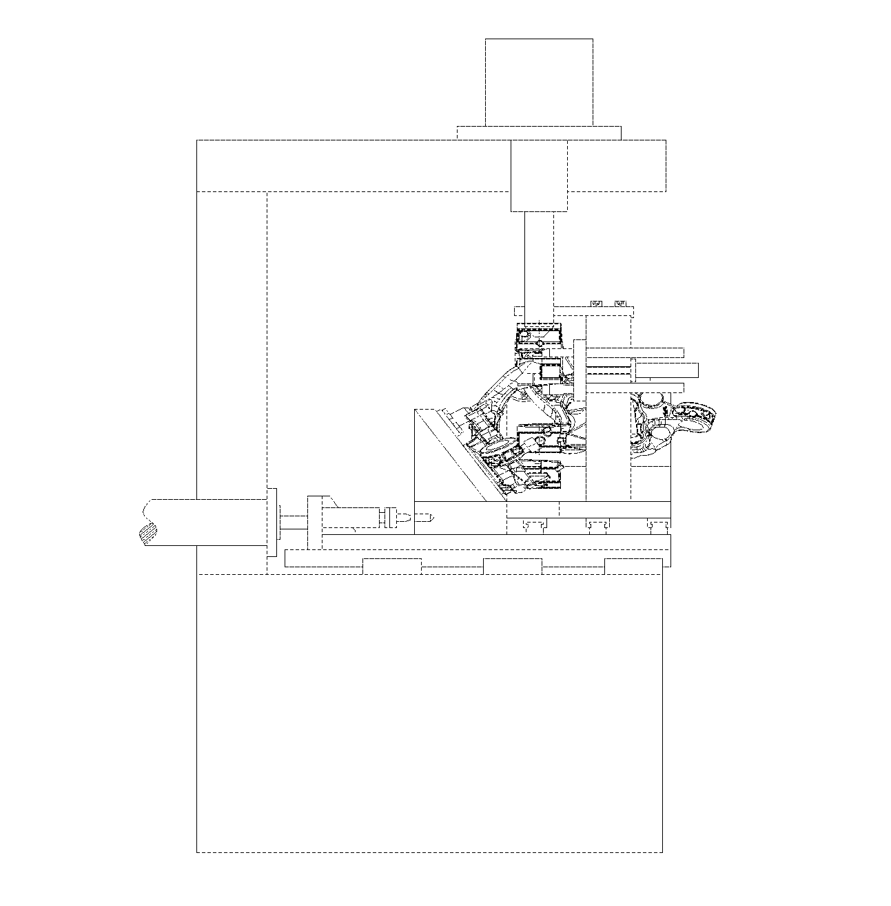
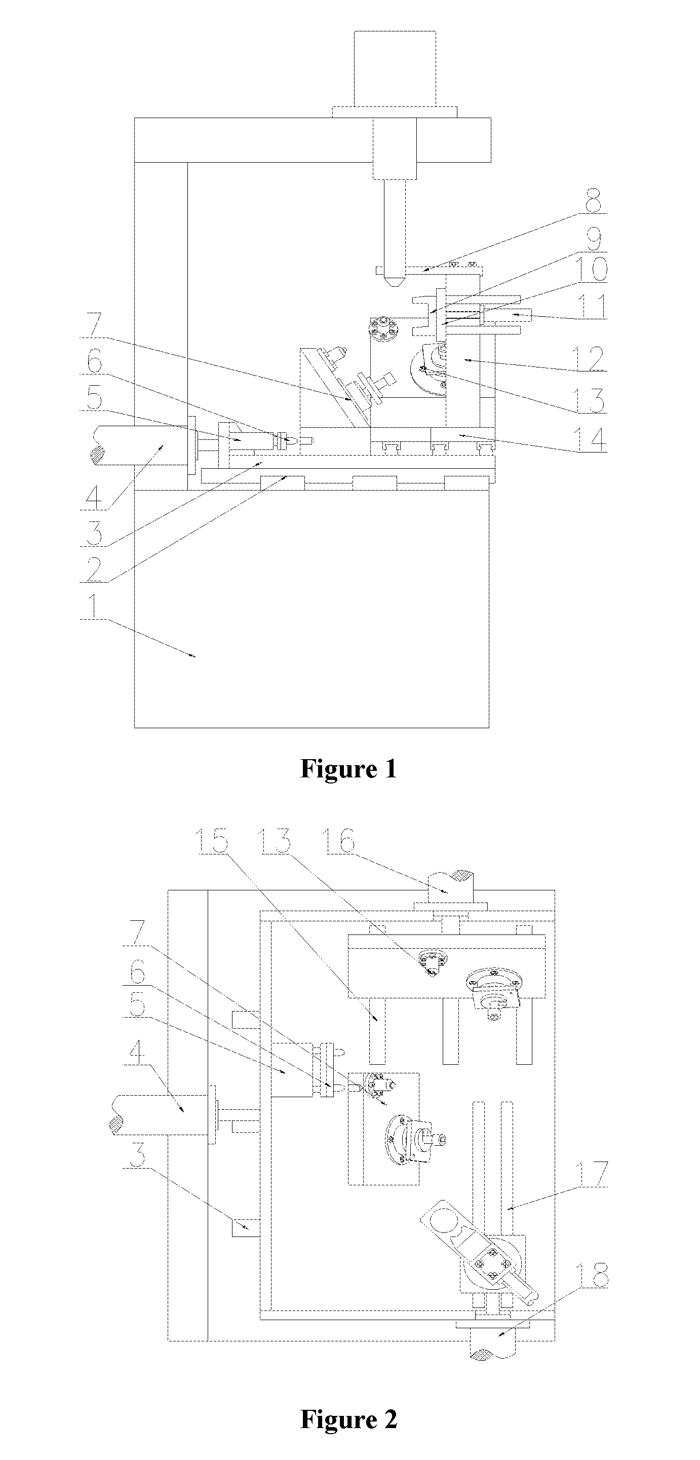
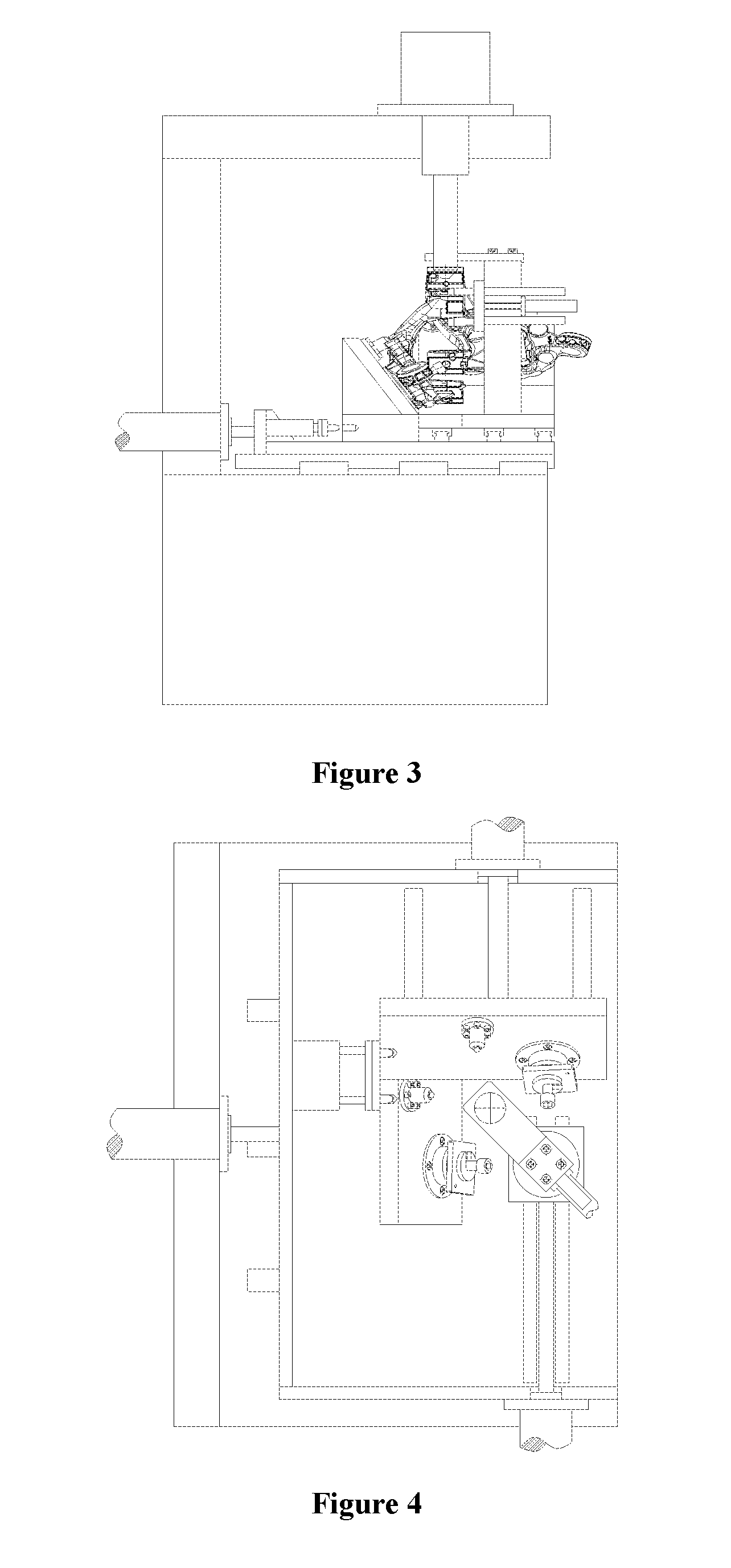
[0012]Details and working conditions of a specific device set forth according to the present invention are described below with reference to the drawings.

[0013]The device consists of a drilling machine 1, a guide rail I 2, a bottom plate 3, a hydraulic cylinder

[0014]I 4, a double-shaft air cylinder 5, a positioning lock 6, a fixture I 7, a feeler block 8, a support block 9, a guide post 10, a hydraulic cylinder II 11, a support post 12, a fixture II 13, a sliding plate 14, a guide rail II 15, a hydraulic cylinder III 16, a guide rail III 17 and a hydraulic cylinder IV 18, wherein the bottom plate 3 is fixed above a worktable of the drilling machine 1 by means of the guide rail I 2; the hydraulic cylinder I 4 is also fixed above the worktable of the drilling machine 1, and the output end of the hydraulic cylinder I 4 is connected with a side vertical plate of the bottom plate 3; the double-shaft air cylinder 5 with the output end provided with the positioning lock 6 is fixed on the s...


PUM


Abstract

Disclosed is a steering knuckle drilling device, including a drilling machine, a bottom plate, guide rails, hydraulic cylinders, fixtures, a support post and a support block. When in use, the present invention can simultaneously drill the left and right symmetric workpieces of a steering knuckle and can conveniently install and dismount the workpieces.

Description

TECHNICAL FIELD[0001]The present invention relates to a machining device, and particularly to a drilling device.BACKGROUND ART[0002]Due to characteristics of the unique spatial structure as well as special functions, the automobile steering knuckle workpiece generally needs the left workpiece and right workpiece to be used in pairs; however, since the left workpiece and right workpiece are different in structure, two sets of fixtures are needed under normal circumstances in machining to respectively machine the left and right workpieces, thus not only increasing the machining cost, but also bringing about adverse impact on the machining efficiency. Even when the left workpiece and right workpiece are fixed on one fixture to be simultaneously machined, it is very inconvenient to install and dismount the workpieces as the limitation of the workpiece structure and the working space exists; the present invention provides a combination fixture, which can satisfy the simultaneous machinin...

Claims


Application Information

Patent Timeline
IPC IPC(8): B23Q3/06B23B41/00
CPCB23B41/00B23Q3/061B23Q3/18B25B1/24B62D7/18Y10T408/563
Inventor XUE, BOWENZHANG, YACONGGUO, JIANDONGLIU, WEIDONGZHENG, YAO
Owner CITIC DICASTAL
Why Eureka
Eureka Blog
Learn More