Setting tool

US20050051592A1Active Publication Date: 2005-03-10HILTI AG

Image

  • Setting tool
  • Setting tool
  • Setting tool

Examples


Embodiment Construction

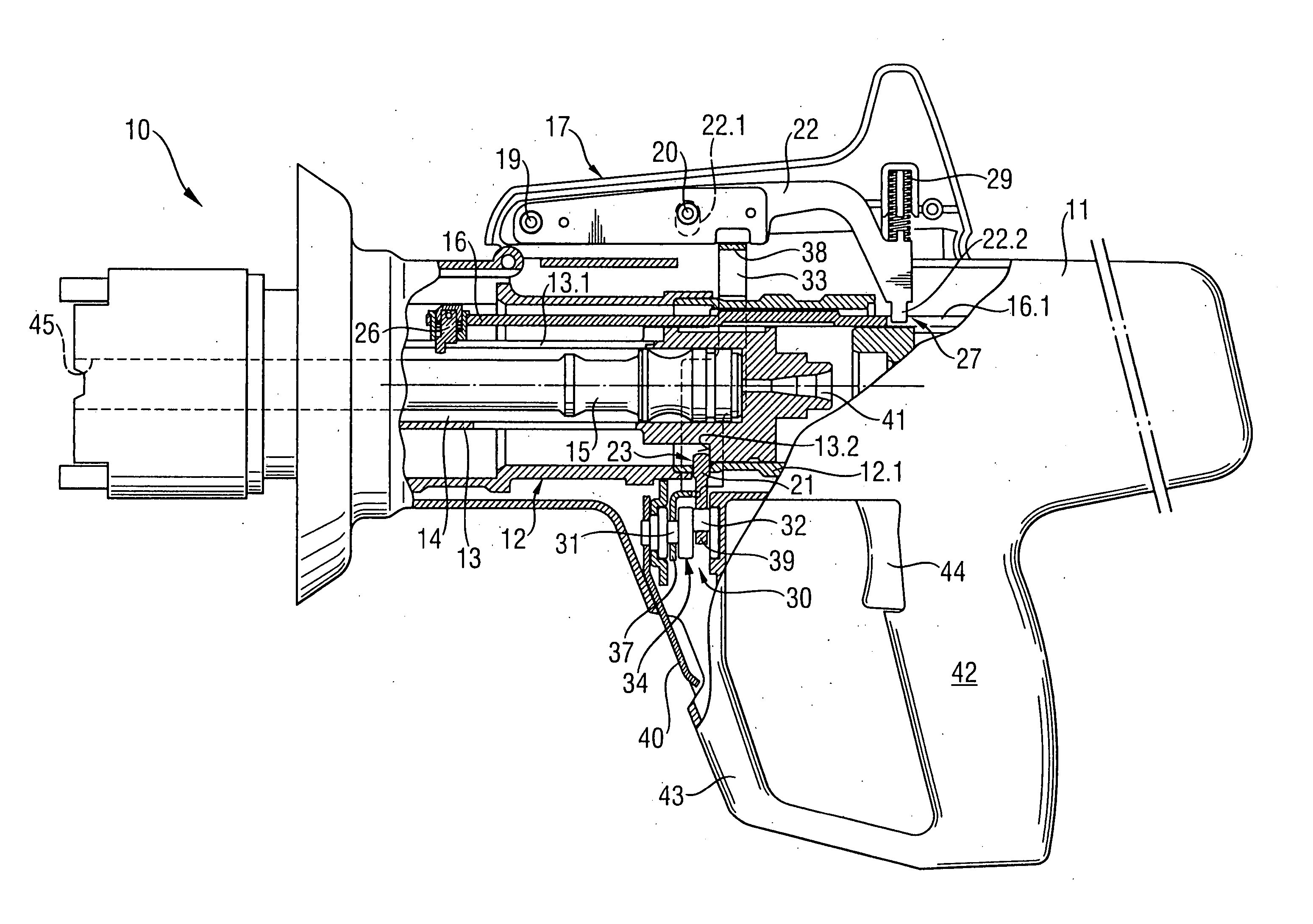
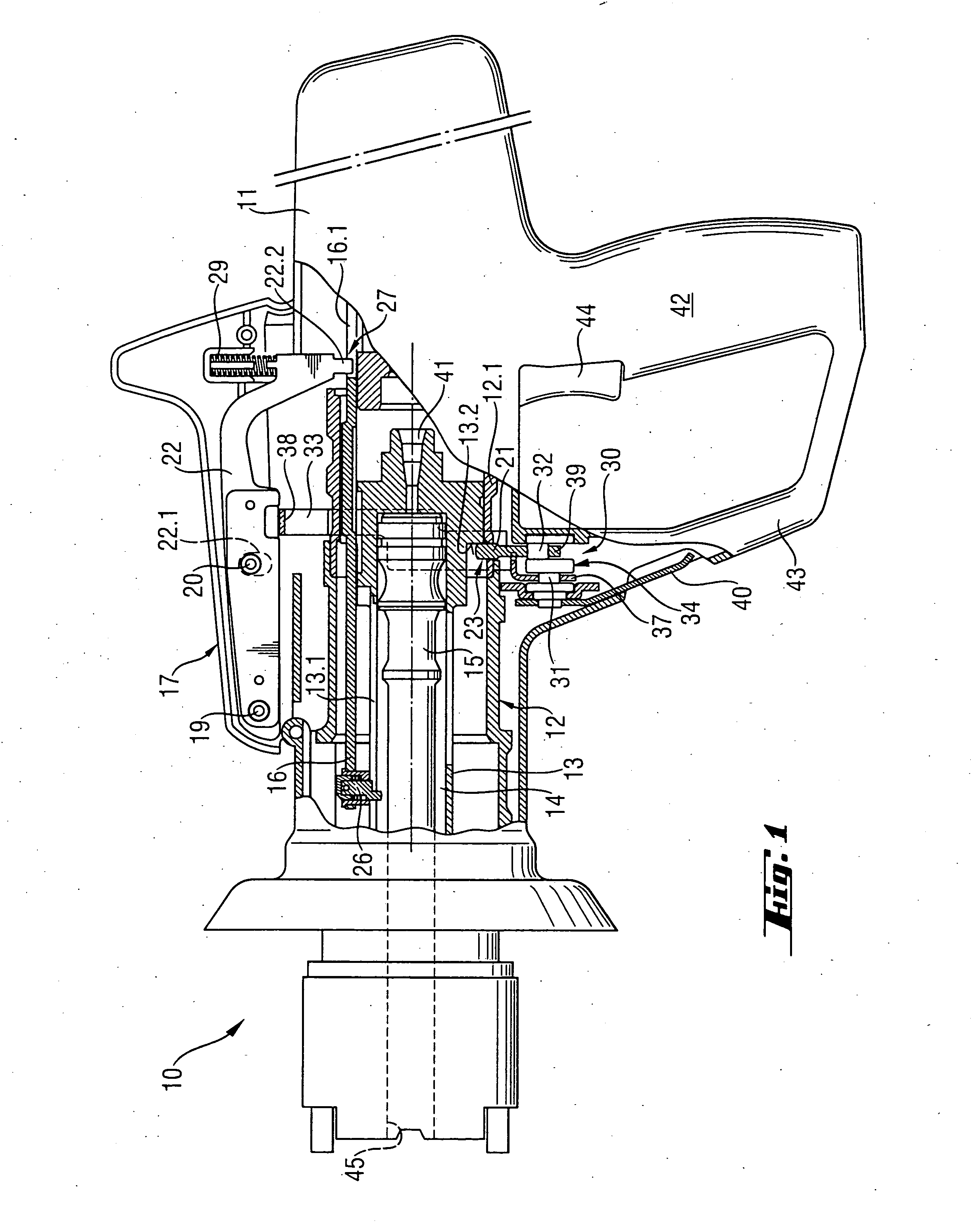
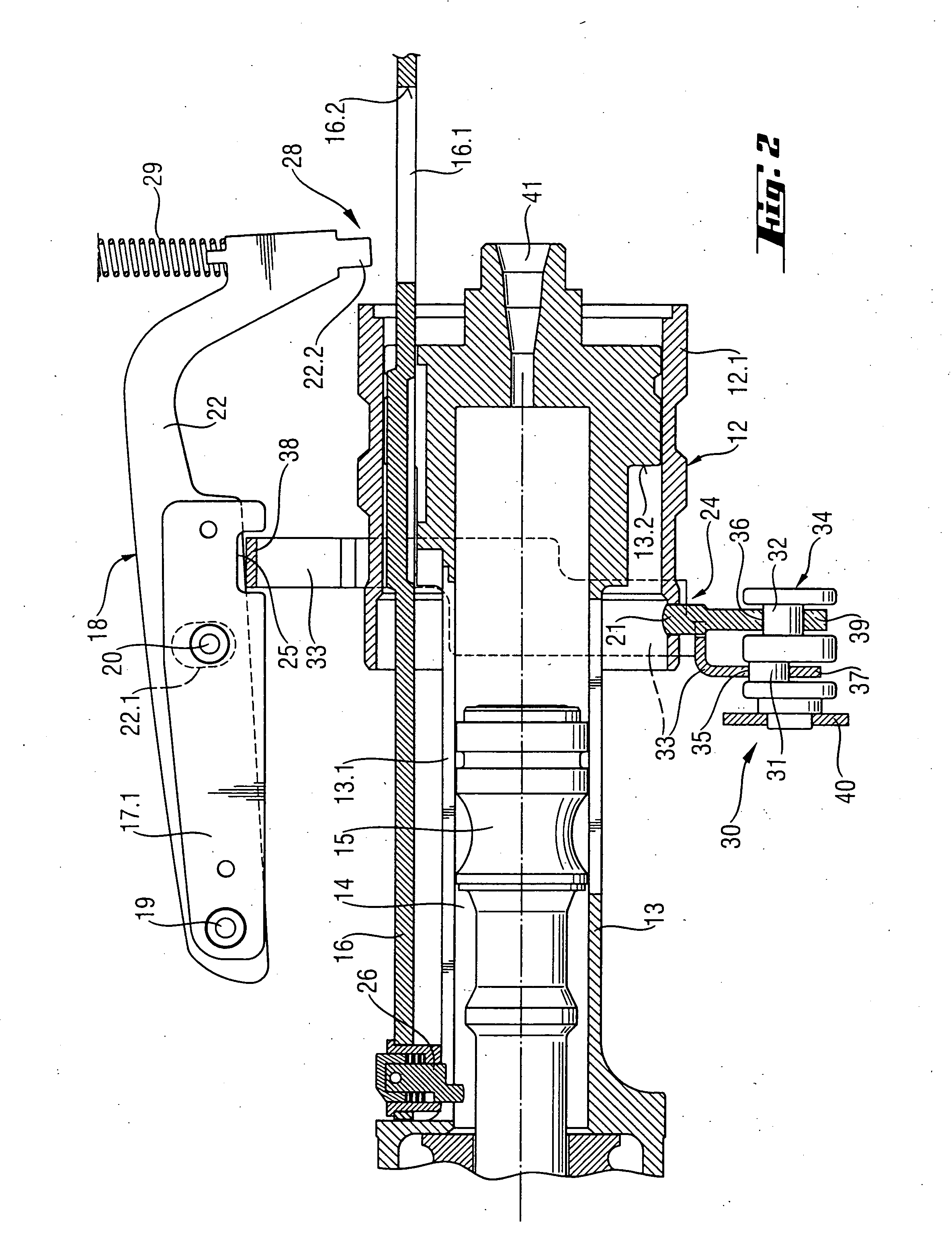
[0020] A setting tool 10 according to the present invention, which is shown in the drawings, includes a one- or multi-part housing 11, a piston guide 13 arranged in the housing 11 and having a hollow chamber 14 in which a setting piston 15 is displaceably arranged. The setting piston 15 is driven by appropriate propellant means or by products of its reaction. In the embodiment of the setting tool 10 shown in the drawings, at the end of the piston guide 13, there is provided a cartridge socket 41 for receiving a propellant charge. The piston guide 13 is arranged in a receptacle 12 of a sleeve-shaped part 12.1 located in the housing 11. The piston guide 13 is displaceably supported in the receptacle 12 against a biasing force of a spring (not shown in the drawings). A setting process of the setting tool 10 is only possible when the setting tool 10 is pressed with its outlet portion 45 against a constructional component or another object. The setting tool 10 is actuated with an actuati...


PUM


Abstract

A setting tool for driving in fastening elements includes a piston guide (13) located in the receptacle (12) and having a hollow chamber (14) in which a setting piston (15) is displaceably arranged, a safety element (21), a piston return element (16), an operational member (17) for operating the piston return element (16), a transmission member (22) for transmitting movement of the operational member (17) to the piston return element (16), and a manually actuatable actuation element (30) having a first adjustment section (31) connected with the safety element (21) and a second adjustment section (32) connected with the transmission member (22) for simultaneous displacement of the safety element (21) and the transmission member (22) in their respective release positions (24, 28) or their safety position (23) and the transmission position (27), respectively.

Description

BACKGROUND OF THE INVENTION [0001] 1. Field of the Invention [0002] The present invention relates to a setting tool for driving in fastening elements and including a housing having a receptacle, a piston guide located in the receptacle and having a hollow chamber in which a setting piston is displaceably arranged, a safety element having a safety position in which it prevents the piston guide from displacing out of the receptacle, and a release position in which the piston guide can be displaced out of the receptacle, a piston return element having a servo component extending into the piston guide, an operational member for operating the piston return element, and a transmission member for transmitting movement of the operational member to the piston return element and having a transmitting position in which it is connected with the piston return element, and a release position in which it is disconnected from the piston return element. [0003] 2. Description of the Prior Art [0004] ...

Claims


Application Information

Patent Timeline
10 Mar 2005
Publication
US20050051592A1
IPC
B25C1/14
CPC
B25C1/143
Inventors
MATTHIESEN, SVEN; BUECHEL, JOHANN