
Driving control system for vehicle

a technology for controlling systems and vehicles, applied in mechanical equipment, transportation and packaging, instruments, etc., can solve problems such as impaired driving, and achieve the effect of suppressing the decrease of driving ability

Active Publication Date: 2015-01-06
TOYOTA JIDOSHA KK
View PDF7 Cites 3 Cited by
  • Summary
  • Abstract
  • Description
  • Claims
  • Application Information

AI Technical Summary

Benefits of technology

The invention provides a system for controlling driving a vehicle that helps prevent decreases in how well it can be driven. This is accomplished by limiting the amount of force provided to the vehicle's wheels at the right times. This system can help improve the vehicle's performance and make it easier to control.

Problems solved by technology

Drivability may be impaired on account of that discrepancy.

Method used


Image

  • Driving control system for vehicle
  • Driving control system for vehicle
  • Driving control system for vehicle

Examples


Embodiment Construction

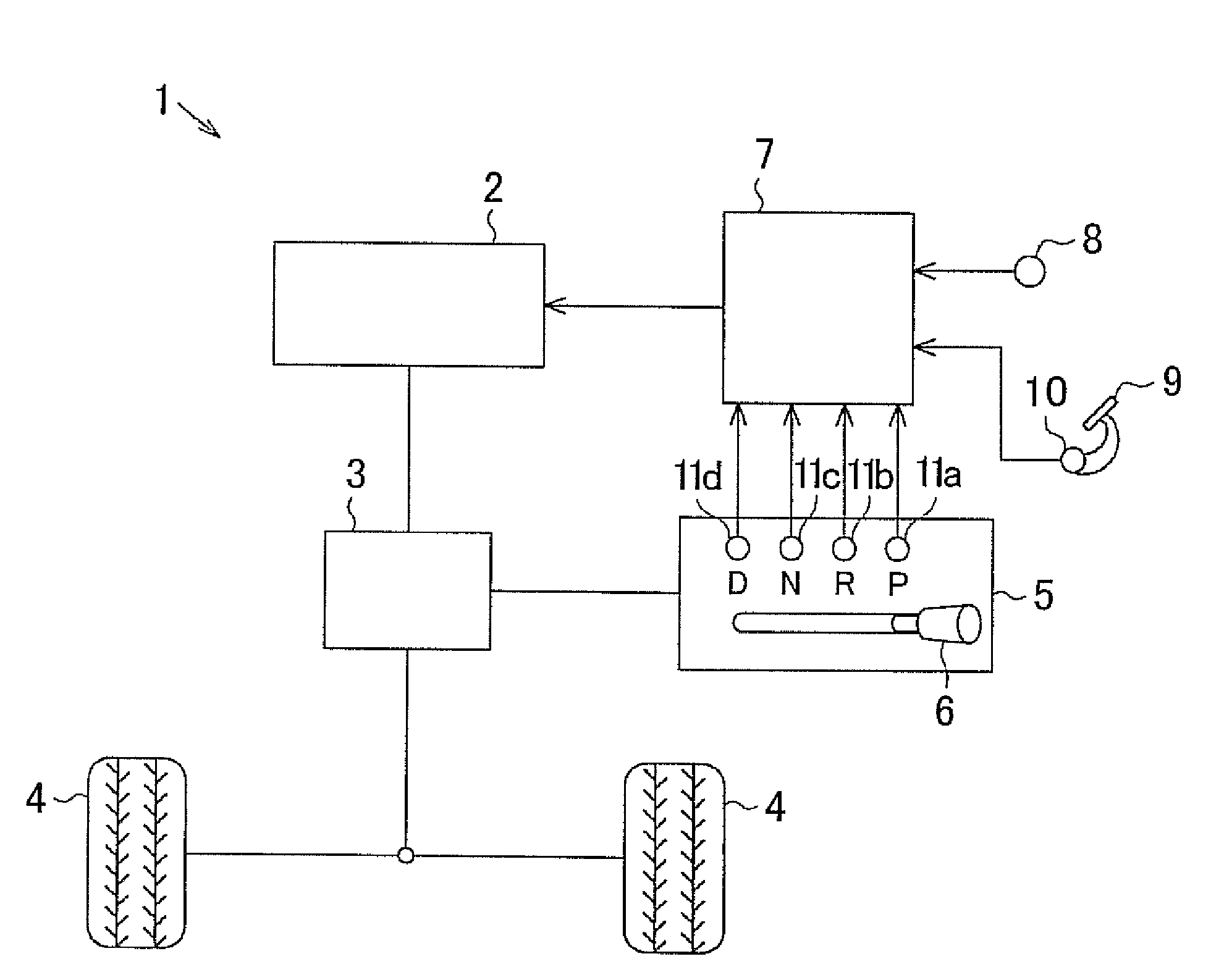
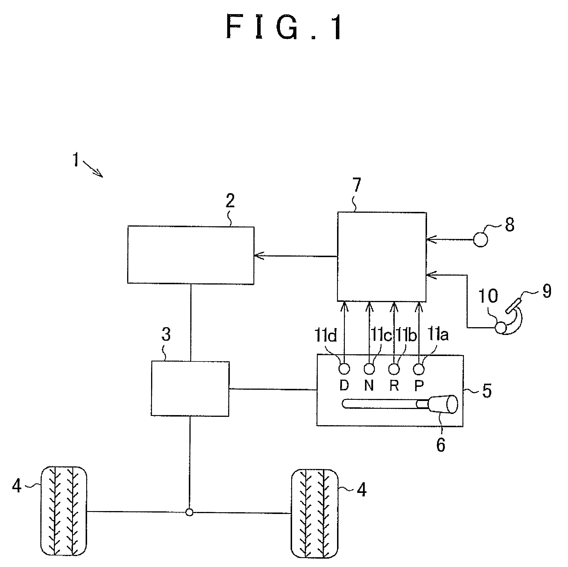
[0022]A specific embodiment of the driving control system for a vehicle according to the invention is explained next. As illustrated in FIG. 1, an internal combustion engine 2 and an automatic transmission 3 are installed in a vehicle 1. The internal combustion engine 2 is a driving source and the automatic transmission 3 performs automatically a shift operation. The internal combustion engine 2 is connected to wheels 4 via the automatic transmission 3. As a result, a driving force outputted by the internal combustion engine 2 is transmitted to the wheels 4 via the automatic transmission 3 and the like. The wheels 4 rotate as a result, thereby enabling travel of the vehicle 1. The automatic transmission 3 is provided with a plurality of gears. The automatic transmission 3 is configured in such a manner that combinations of the plurality of gears can be modified so as to select any one from among a plurality of gear positions established beforehand. The automatic transmission 3 can t...


PUM


Abstract

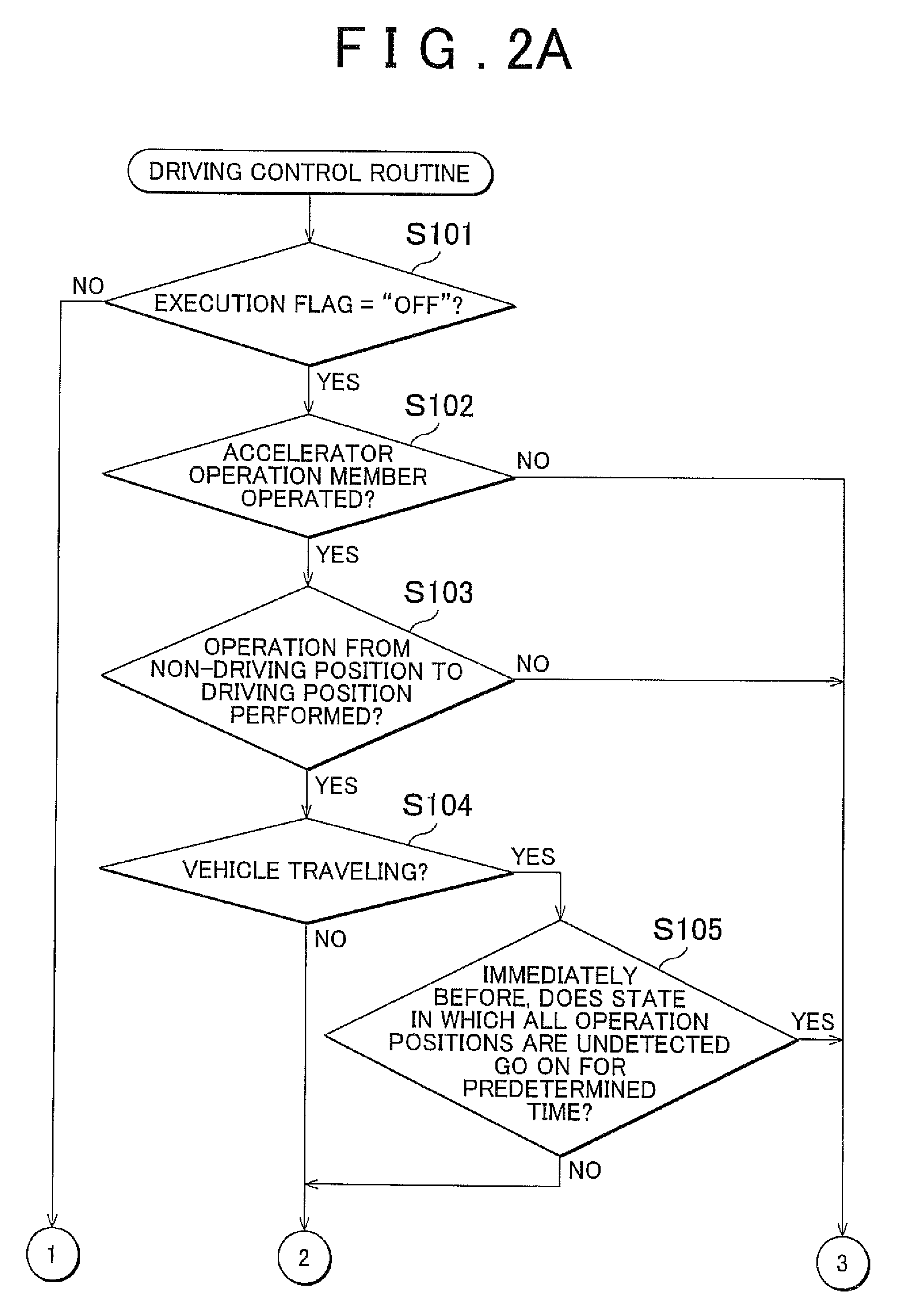
A vehicle has a shift mechanism and a position detection device that detects an operation position of the shift mechanism. A transmission is brought to a power transmission state when an operation unit of the shift mechanism is operated to a driving position, and is brought to a power interrupt state when the operation unit is operated to a non-driving position. A driving force limitation process for reducing the driving force of an internal combustion engine is executed when it is determined that the non-driving position has been shifted to the driving position on the basis of the operation position of the operation unit as detected by the position detection device. The driving force limitation process is prohibited when it is determined that the vehicle is traveling and that the operation unit is not operated to any of the operation positions.

Description

[0001]The disclosure of Japanese Patent Application No. 2011-280385 filed on Dec. 21, 2011 including the specification, drawings and abstract is incorporated herein by reference in its entirety.BACKGROUND OF THE INVENTION[0002]1. Field of the Invention[0003]The invention relates to a driving control system for vehicles.[0004]2. Description of Related Art[0005]Motors such as internal combustion engines and electric motors are installed as driving sources, in vehicles such as automobiles. Such motors are coupled to wheels through a transmission. The vehicle is provided with a shift mechanism that allows switching, in response to an operation by the driver, between a driving position (for instance, a position such that the vehicle travels forward, or a position such that the vehicle travels in reverse) and a non-driving position (for instance, a parking position or a neutral position).[0006]An operation lever, as an operation unit of the shift mechanism, is coupled to the abovementione...

Claims


Application Information

Patent Timeline
Patent Type & Authority Patents(United States)
IPC IPC(8): G06F7/00G06F17/00G06F19/00B60W10/06B60W10/10B60W10/11B60W30/18B60W30/184F16H59/18F16H63/50
CPCB60W30/18027B60W30/18B60W10/10F16H63/50B60W30/1846B60W10/11B60W30/18009B60W2710/0666B60W2540/16B60W2540/165B60W2710/083B60W2540/10B60W10/06B60W2520/10F16H59/18F16H2063/508
Inventor MINASE, YUKITAKAGI, MASASHIOHBAYASHI, MOTONARISHIMADA, HIROSHITAKAGI, TOSHIHIRO
Owner TOYOTA JIDOSHA KK
Learn More