
Road milling machine

a milling machine and road technology, applied in cutting machines, roads, construction, etc., can solve the problems of the operating direction of the milling machine where the risk of ejection of milled materials exists, and achieve the effect of improving the material transportation of milled materials

Active Publication Date: 2015-01-27
WIRTGEN GMBH
View PDF12 Cites 4 Cited by
  • Summary
  • Abstract
  • Description
  • Claims
  • Application Information

AI Technical Summary

Benefits of technology

The solution improves material transport efficiency by reducing packing density and power requirements, while minimizing wear and preventing material compaction, allowing for smoother operation and effective material collection by the transport arrangement.

Problems solved by technology

In particular, the risk of ejection of milled material exists in the operating direction of the milling machine if the milling drum is rotated in the direction opposite to the operating direction.

Method used


Image

  • Road milling machine
  • Road milling machine
  • Road milling machine

Examples


Embodiment Construction

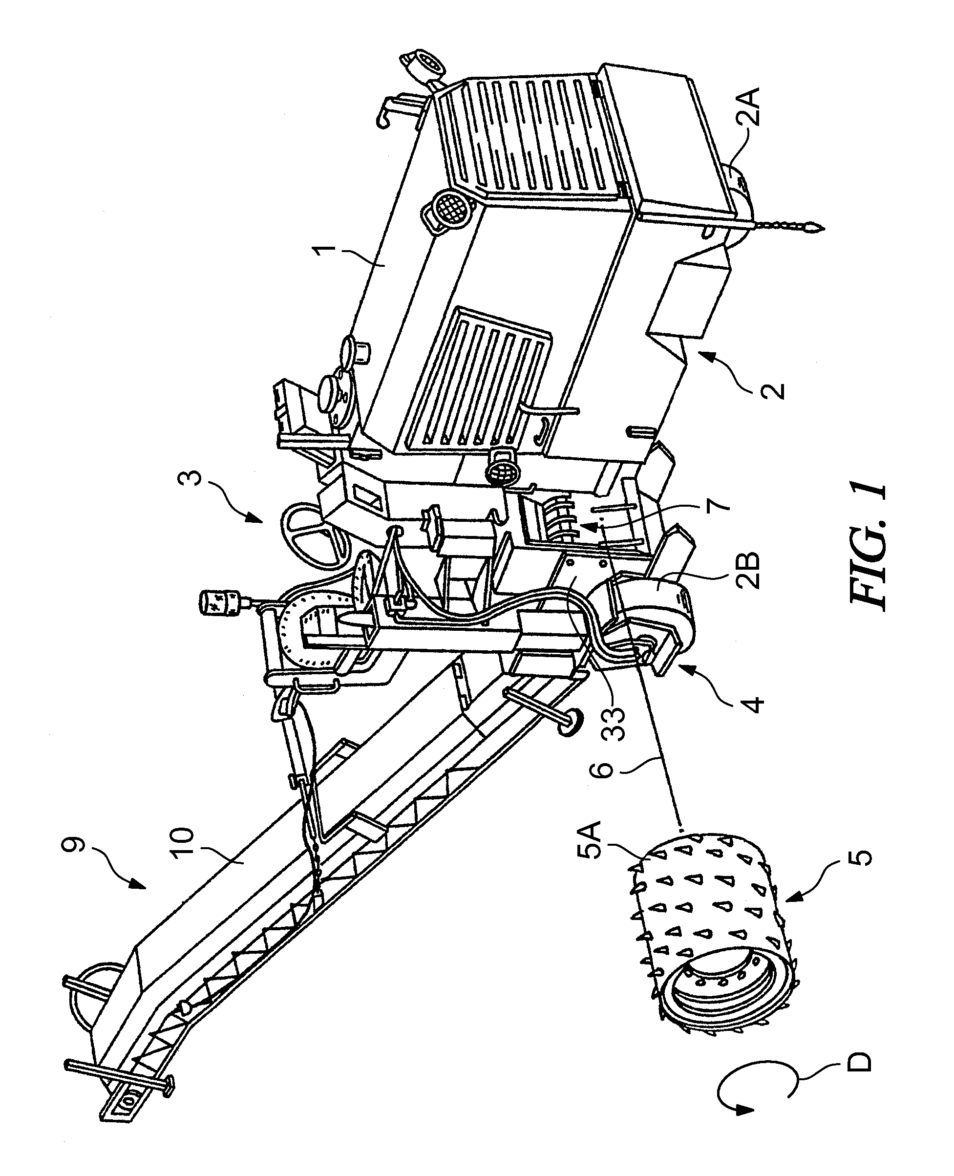
[0041]FIG. 1 shows in a perspective view a road milling machine, specifically a rear loader road milling machine. The road milling machine comprises a machine frame 1, which is supported by a chassis 2. The chassis 2 has a front wheel 2A and two rear wheels 2B, when seen in the operating direction. The operator's platform 3 is in the rear part of the machine frame. The milling mechanism 4 of the road milling machine is underneath the operator's platform 3.

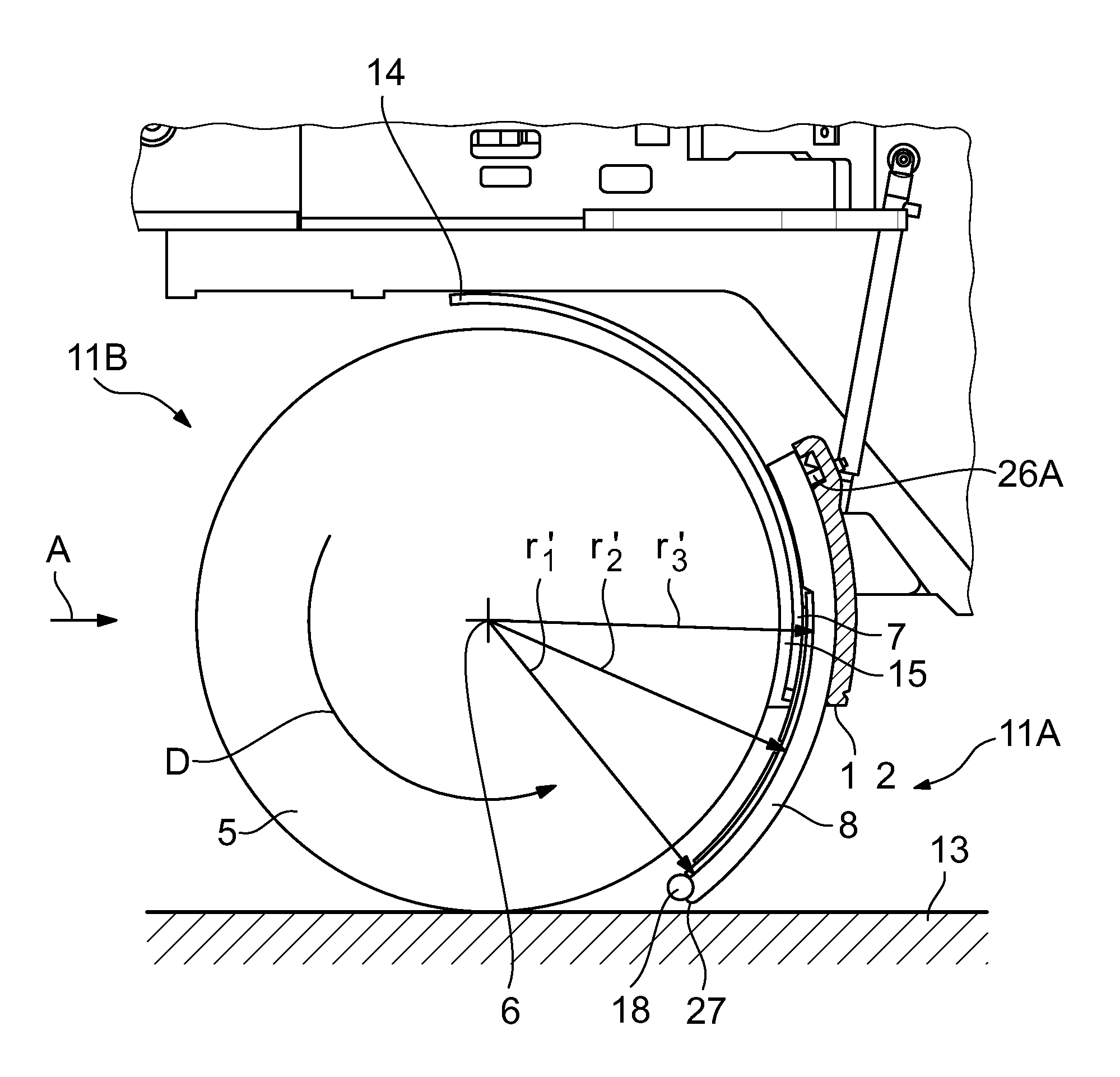
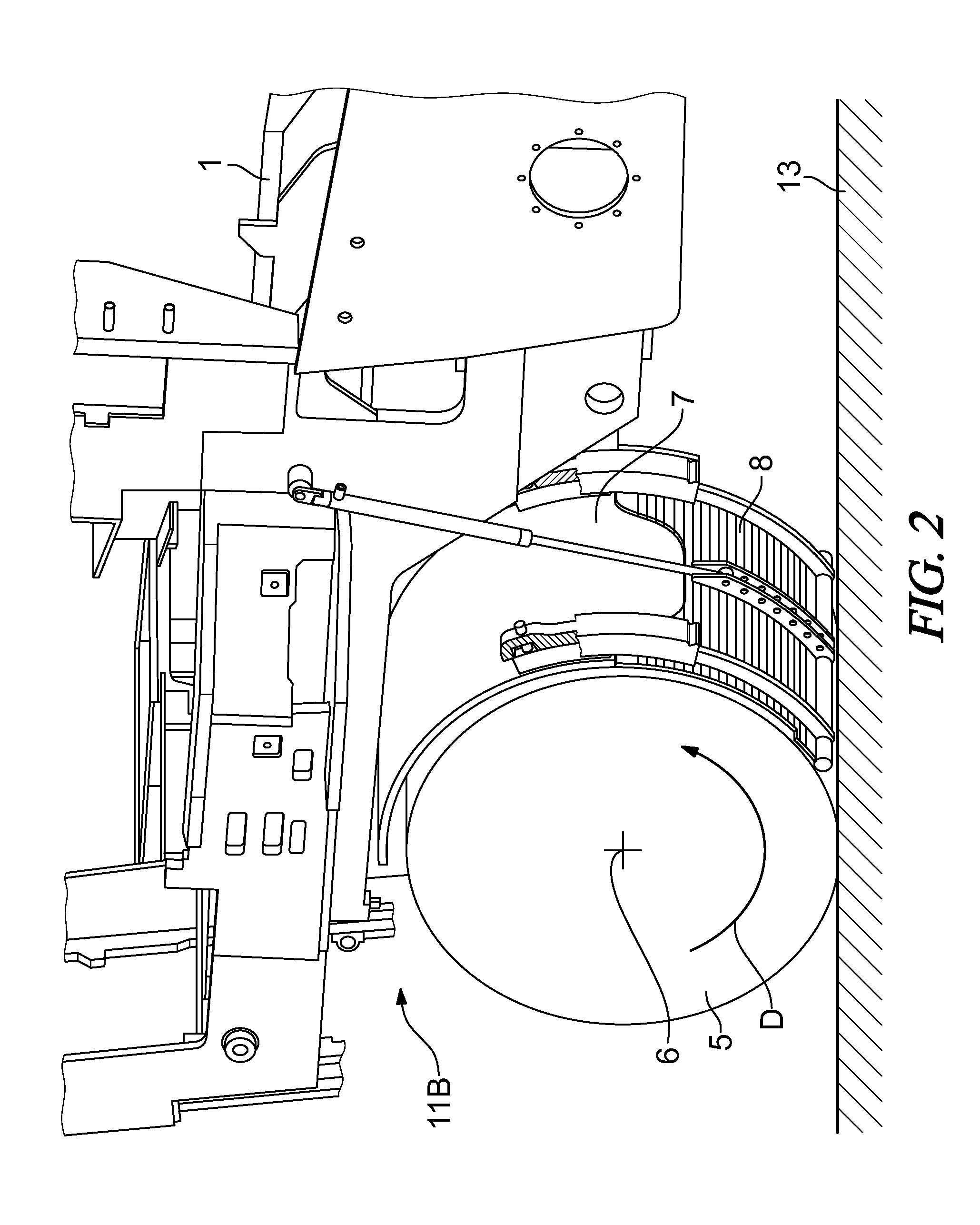
[0042]The milling mechanism 4 comprises a milling drum 5, with cutting tools 5A spaced around its periphery. The milling drum 5 is positioned in a milling drum housing 7 about an axis of rotation 6 running transverse to the operating direction of the milling machine. The milling drum 5 rotates in the milling drum housing 7 in a predetermined direction of rotation D. In the present example, the milling drum 5 rotates in a counter-clockwise direction. The milling drum housing 7 enclosing the milling drum 5 has a discharge opening at ...


PUM


Abstract

The invention relates to a road milling machine, with a milling drum housing partially surrounding a milling drum, wherein the opening between the milling drum housing and the surface of the material to be milled can be closed off by a hold-down device. The distance between the axis of rotation and the hold-down device increases in the specified direction of rotation of the milling drum at least over a section of the gap between the milling drum and the hold-down device. The particular configuration of the hold-down device leads to an improvement in transport of the milled material to the transport arrangement. The gap width increasing in the direction of rotation of the milling drum improves material flow with a relatively small power requirement and relatively low wear of the milling drum.

Description

BACKGROUND OF THE INVENTION[0001]1. Field of the Invention[0002]The invention relates to a road milling machine with a machine frame and a milling mechanism for milling off material.[0003]2. Description of the Prior Art[0004]The known road milling machines have a machine frame, which is supported by a chassis, and a milling mechanism, which comprises a milling drum for milling off material. The milling drum, which is rotatable about an axis transverse to the operating direction, is located in a milling drum housing.[0005]Furthermore, the known road milling machines have a transport arrangement for conveying the milled material. In the known rear loader road milling machines, the transport arrangement is behind the milling drum housing, when seen in the operating direction, to allow it to feed the milled material, as far as possible free from residues, over the rear of the milling machine to the following truck. A rear loader road milling machine is known, for example, from DE 195 47...

Claims


Application Information

Patent Timeline
Patent Type & Authority Patents(United States)
IPC IPC(8): E01C23/088
CPCE01C23/088E01C23/127
Inventor FRANZMANN, DIRKBERNING, CHRISTIANLEY, HERBERTBARIMANI, CYRUSHAHN, GUNTER
Owner WIRTGEN GMBH
Learn More