Safety control system for an electromagnetic door lock of an electric household appliance

a safety control and door lock technology, applied in the direction of other washing machines, cleaning equipments, tableware washing/rinsing machine details, etc., can solve the problems of large size, complex and costly known devices described above, etc., to eliminate dead times, simplify mechanical devices, and reduce costs.

Active Publication Date: 2015-02-10
ILLINOIS TOOL WORKS INC
View PDF8 Cites 1 Cited by
  • Summary
  • Abstract
  • Description
  • Claims
  • Application Information

AI Technical Summary

Benefits of technology

[0008]It is an object of the present invention to provide a simple, cost-effective and small-sized control system which is however safe; in particular, considering that the control pulses of the electromagnet are generally produced by a TRIAC, it is an object to provide a control system which is able to neutralize possible malfunctions of the TRIAC with a consequent undesired pulse emissions. It is a further object of the invention to provide a safety control method for an electromagnetic door lock which may use a highly simplified mechanical device, and which allows to obtain a nearly immediate releasing of the door at the end of the operating cycle of the electric household appliance, so as to eliminate the dead times due to the time needed for the thermistor to cool down.
[0019]Furthermore, blocking and releasing the door may be easily achieved several times during the operating cycle of the electric household appliance, e.g. according to the speed of the drum in case of a washing machine or drying machine, thus allowing the user to open the door during the washing cycle for checking or adding previously forgotten garments or washing additives. Furthermore, at the end of the operating cycle, a nearly instantaneous release of the door is obtained, considering that the emission of the pulse train terminates while the drum is still running (although at slow speed), thus giving time to the PCT element to cool down before fully stopping the drum itself.

Problems solved by technology

The known device described above is complex and costly, as well as large in size.

Method used


Image

  • Safety control system for an electromagnetic door lock of an electric household appliance
  • Safety control system for an electromagnetic door lock of an electric household appliance

Examples


Embodiment Construction

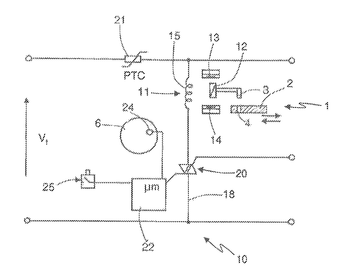
[0023]With reference to FIG. 1, numeral 1 indicates as a whole an electromagnetic door lock comprising a slide 2 adapted to cooperate with the notch of the door to be released (not shown) in a known manner, and a sliding pawl 3 of known type and adapted to selectively assume a blocking position, in which it engages a perforation 4 of slide 2, and a releasing position in which it does not engage the perforation 4, thus leaving slide 2 free to slide in the direction of the arrows.

[0024]The door lock 1 is intended to equip an electric household appliance, e.g. a washing machine and / or drying machine and / or dishwasher, not shown, provided with a rotating drum 6, for example, and is controlled by a safety control system, indicated by numeral 10 as a whole.

[0025]According to the invention, the safety control system 10 for the door lock 1 comprises an electromagnet 11, its core 12 controlling the position of the pawl 3, e.g. by being directly connected to the core 12.

[0026]In the illustrat...


PUM


Abstract

A safety control system for an electromagnetic door lock of an electric household appliance, wherein a blocking pawl is controlled by the movement of a core of an electromagnet, including a supplying circuit of a coil of the electromagnet, power supplying means to supply electric pulses in the circuit for energizing the coil and a PTC element arranged in series in the circuit; wherein power supplying means are of the type adapted to generate first pulses for taking the pawl to a blocking position and second pulses, having a polarity opposite to the first, for taking the pawl to a releasing position; and including means for determining, according to the parameters of an operating cycle of the electric household appliance, the emission of at least one train of first pulses by the power supplying means, so as to produce the heating of the PTC element.

Description

RELATED APPLICATIONS[0001]The present application is national phase of PCT / US2009 / 066731 filed Dec. 4, 2009, and claims priority from Italian Application Number TO2008A000905 filed Dec. 5, 2008.TECHNICAL FIELD[0002]The present invention relates to a safety control system for an electromagnetic door lock of an electric household appliance, in particular a washing machine and / or drying machine provided with a rotating drum, or even a dishwasher, as well as to a safety control method for the mentioned door lock.BACKGROUND ART[0003]It is known that the doors of electric household appliances in which a washing cycle is carried out, in particular those of washing machines / drying machines / dishwashers, are blocked in use in a closed position by a blocking device provided with a safety device which is released only either at the end of the washing cycle or in all cases when the rotating drum of the electric household appliance is either still or turns at a speed which is not dangerous for th...

Claims


Application Information

Patent Timeline
Patent Type & Authority Patents(United States)
IPC IPC(8): H02H11/00A47L15/42D06F37/42D06F39/14
CPCD06F37/42A47L15/4259D06F39/14Y10T70/5155D06F34/10
Inventor BOSTJAN, BERGINC
Owner ILLINOIS TOOL WORKS INC
Why Eureka
Try Eureka