
Plural focal-plane imaging

a focal plane and imaging technology, applied in the field of imaging systems, can solve the problems of complex image sensor and image processing, and is not suitable for certain applications,

Active Publication Date: 2015-02-10
DIGIMARC CORP
View PDF16 Cites 9 Cited by
  • Summary
  • Abstract
  • Description
  • Claims
  • Application Information

AI Technical Summary

Benefits of technology

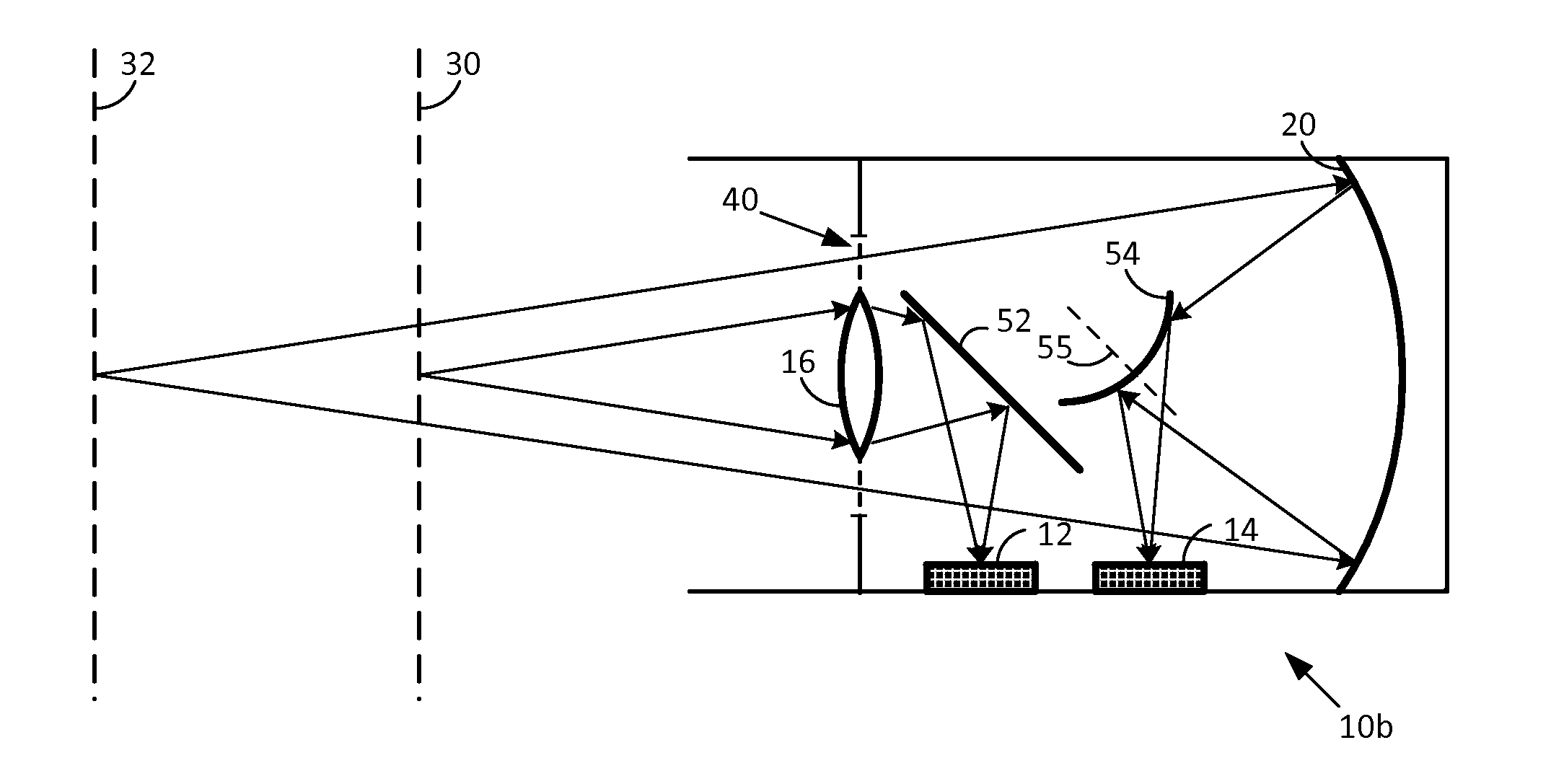
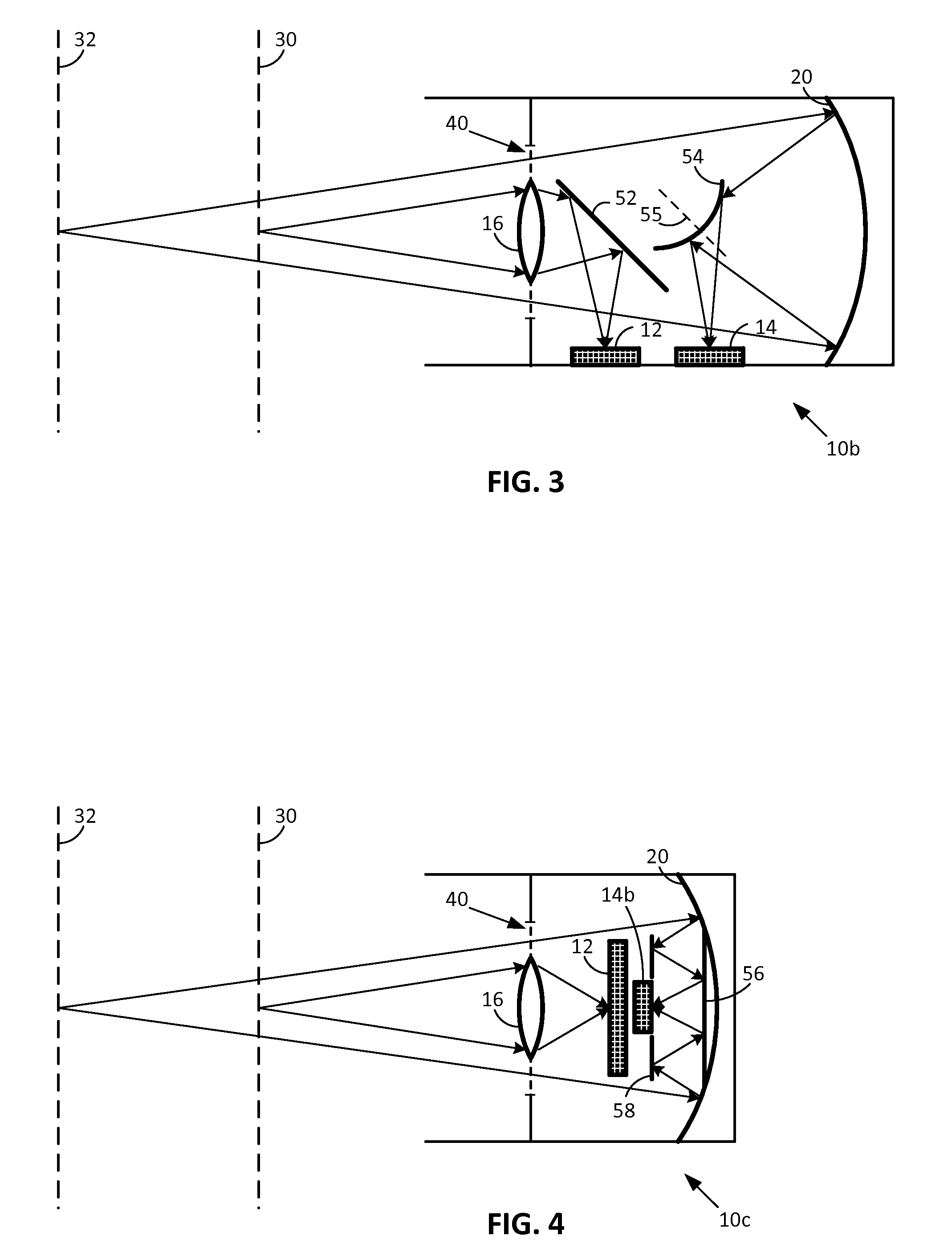
The present technology is about capturing imagery from two or more focal planes using a single camera. The technology allows for relaxed single focal plane restriction of conventional cameras without the complexity of plenoptic or light field approaches. The camera includes first and second image sensors and light-transmitting lenses that cooperate to capture images from two focal planes. The two focal planes can be parallel and spaced-apart, or can be at different distances from the lens. The technology provides a way to capture focused imagery from two or more focal planes simultaneously, without the complexity of plenoptic or light field approaches.

Problems solved by technology

However, the twin optical systems in these arrangements typically capture imagery from a single focal plane.
However, the detailed arrangements have disadvantages which make them ill-suited for certain applications.
While advantageous in many respects, such arrangements require complex image sensors and image processing.

Method used


Image

  • Plural focal-plane imaging
  • Plural focal-plane imaging
  • Plural focal-plane imaging

Examples


Embodiment Construction

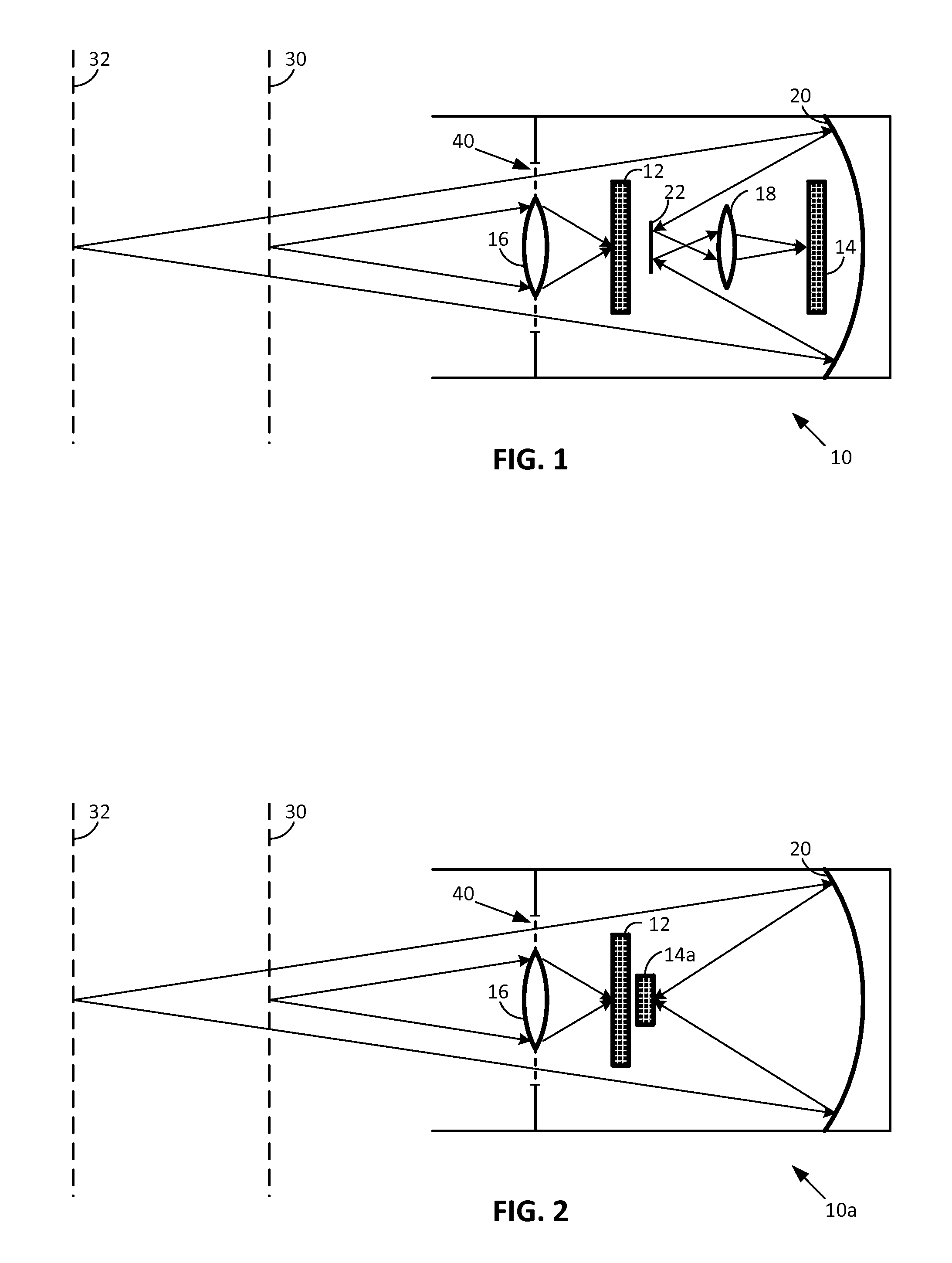
[0009]Referring to FIG. 1, an illustrative camera apparatus 10 includes first and second image sensors 12 and 14, first and second light-transmitting lenses 16 and 18, and first and second mirrors (reflectors) 20 and 22. These elements cooperate to define two collinear imaging systems—each with a respective optical path.

[0010]The first imaging system comprises first sensor 12, and first lens 16. These elements cooperate to capture an image that is projected onto the first sensor from a first focal plane 30.

[0011]The second imaging system comprises second sensor 14, and first and second mirrors 20 and 22. These elements cooperate to capture an image that is projected onto the second sensor 14 from a second focal plane 32. (While mirror 22 is shown as planar, it can take various forms depending on the particular design, e.g., parabolically curved (Gregorian), hyperbolically curved (Casssegrain), spherically curved, etc.)

[0012]As can be seen, the two focal planes 30 and 32 are parallel...


PUM


Abstract

An imaging system captures focused imagery from two or more focal planes, yet does so with relatively simple optical elements. Some arrangements involve folded optical paths, to make them more compact in size. Others enable the image sensors to be mounted in coplanar arrangement. Still others involve digital compositing, e.g., to mitigate undesired bokeh effects. A great variety of other features and arrangements are also detailed.

Description

TECHNICAL FIELD[0001]The present technology concerns imaging systems.INTRODUCTION[0002]Various arrangements are known that integrate telephoto and wide angle optical systems into a single apparatus—either using a single image sensor, or two image sensors. Examples are shown in U.S. Pat. Nos. 5,051,830, and 7,486,438, and in patent publication 20100214468. However, the twin optical systems in these arrangements typically capture imagery from a single focal plane.[0003]U.S. Pat. No. 7,764,440 discloses technology for capturing imagery from two focal planes simultaneously. However, the detailed arrangements have disadvantages which make them ill-suited for certain applications.[0004]Cameras are commercially available, from Lytro and Pelican Imaging, that allow users to change the focus of a picture after it has been captured. (Such cameras employ plenoptic and light field sensing.) While advantageous in many respects, such arrangements require complex image sensors and image processing...

Claims


Application Information

Patent Timeline
Patent Type & Authority Patents(United States)
IPC IPC(8): H04N5/225G02B13/16
CPCH04N5/272H04N23/50H04N23/54
Inventor KAMATH, AJITH
Owner DIGIMARC CORP
Learn More