AI technical title is built by Patsnap AI team. It summarizes the technical point description of the patent document.
a technology of surgical staples and stapling devices, which is applied in the field of surgical staples, can solve the problems of narrow and long staples used in such procedures
Active Publication Date: 2015-02-17
TYCO HEALTHCARE GRP LP
View PDF65 Cites 1333 Cited by
Summary
Abstract
Description
Claims
Application Information
AI Technical Summary
This helps you quickly interpret patents by identifying the three key elements:
Problems solved by technology
Method used
Benefits of technology
Benefits of technology
[0026]The end effector may further include a biasing member interposed between each staple cartridge segment and the first jaw. The biasing members may maintain each staple cartridge segment spaced a distance from the first jaw.
[0030]The end effector may further include a biasing member interposed between each staple cartridge segment and the first jaw. The biasing members may maintain each staple cartridge segment spaced a distance from the first jaw.
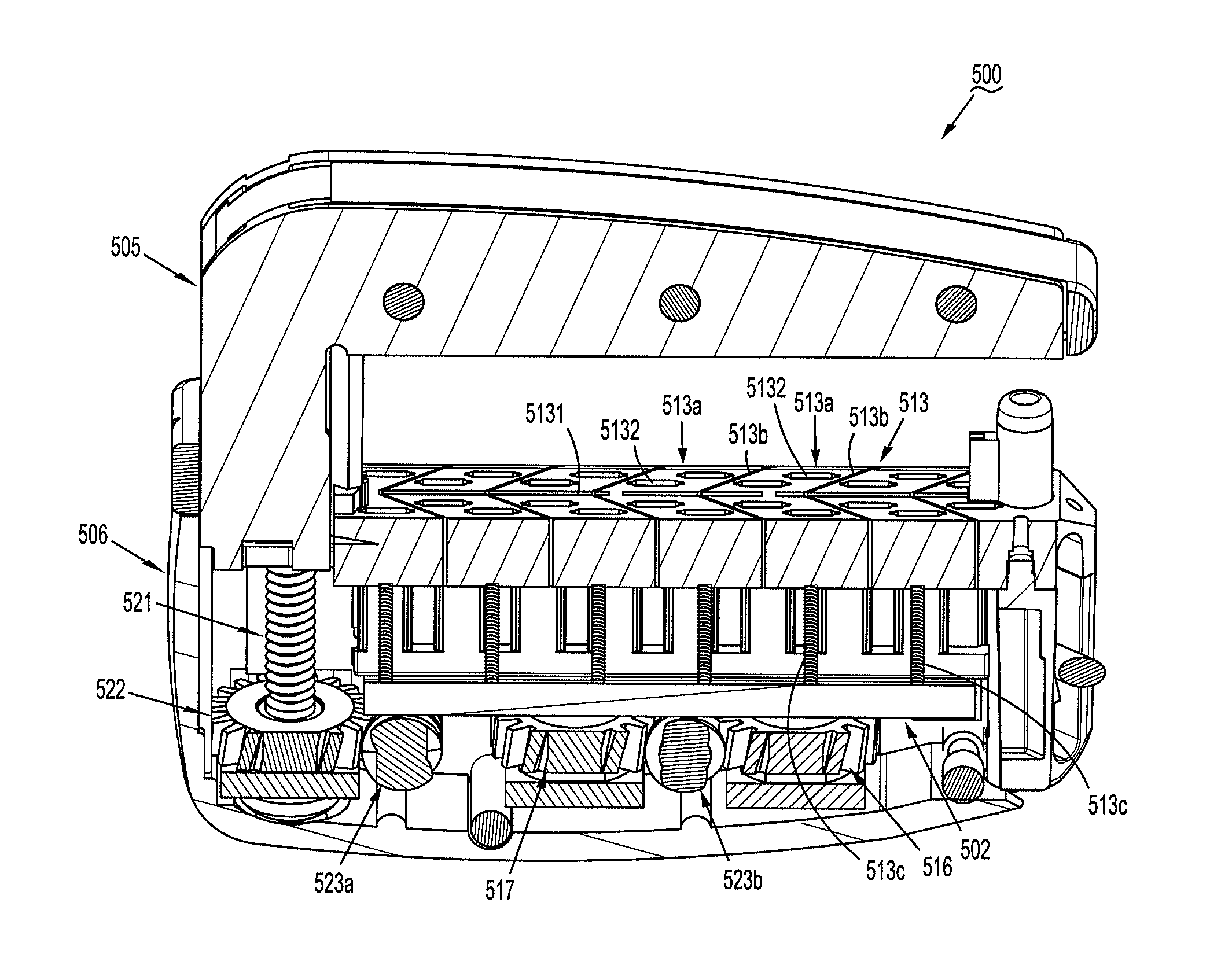
[0037]One or more electrical traces may be positioned on a bottom surface of one of the staple forming pockets. Each electrical trace may be electrically isolated from any other electrical traces. One or more of the staple forming pockets may include two or more recesses and one or more electrical traces positioned within each recess of the one or more staple forming pockets. The one or more electrical traces are operably coupled to one or more of a resistor, an inductor, a capacitor, a Piezo-Electric Crystal, and a transducer. One or more of the plurality of staples is configured to interrupt the one or more electrical traces as the one or more staples are formed in the one or more staple forming pockets such that the interruption of the one or more electrical traces facilitates the communication of the signal to the controller. One or more of the first and second legs of one or more of the staples of the plurality of staples may be driven into the one or more electrical traces with sufficient force to break the one or more electrical traces.
[0048]The surgical stapling apparatus may include a controller in electrical communication with the pressure sensing element. The controller is configured to identify unsafe loads along the staple guide based upon a first signal transmitted from the pressure sensing element and generate a second signal to the surgical stapling apparatus to prevent firing and / or clamping of the surgical stapling apparatus when an unsafe load is identified by the controller.
Problems solved by technology
Moreover, laparoscopic and endoscopic procedures often require the surgeon to access organs, tissues and / or vessels far removed from the incision.
Thus, apparatuses used in such procedures are typically long and narrow while being functionally controllable from a proximal end of the apparatus.
Method used
Image
Click on the blue label to locate the original text in one second.
Reading with bidirectional positioning of images and text.
Examples
Embodiment Construction
[0088]Embodiments of the presently disclosed surgical stapling apparatus will now be described in detail with reference to the drawings, in which like reference numerals designate identical or corresponding elements in each of the several views.
[0089]As shown in the drawings and as described throughout the following description, and as is traditional when referring to relative positioning on an object, the term “proximal” refers to the end of the apparatus that is closer to the user and the term “distal” refers to the end of the apparatus that is farther from the user. In the following description, well-known functions or constructions are not described in detail to avoid obscuring the present disclosure in unnecessary detail.
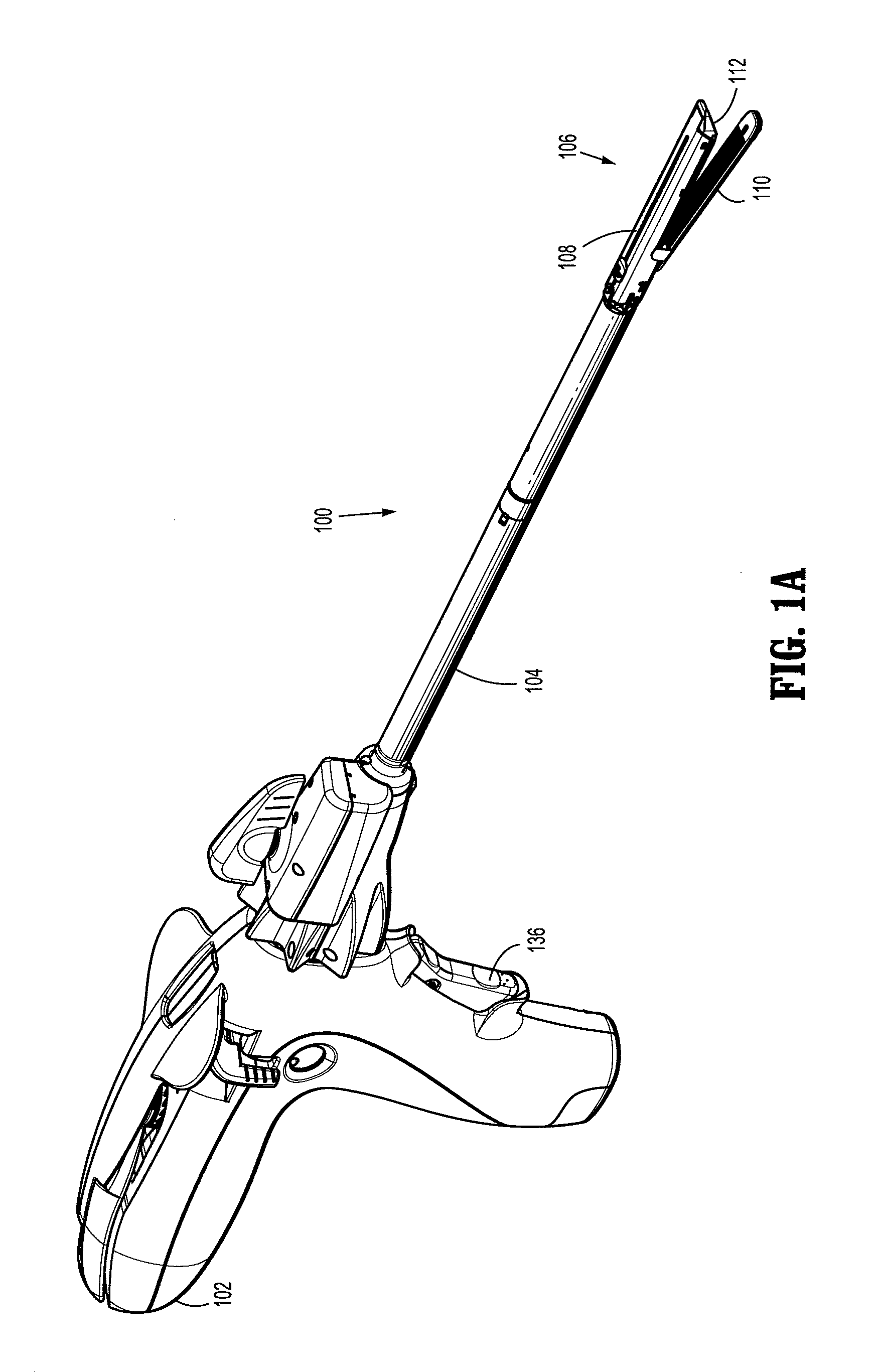
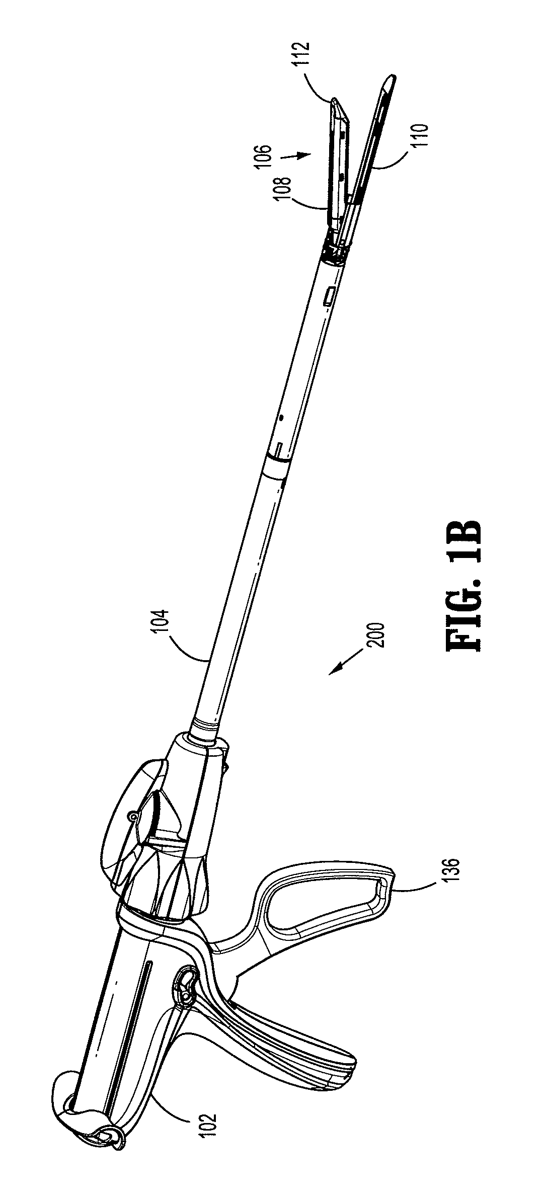
[0090]FIG. 1A illustrates a powered surgical stapling apparatus shown generally as 100. FIG. 1B illustrates a manual surgical stapling apparatus shown generally as 200. Briefly, surgical stapling apparatus 100, 200 includes a housing 102 having an actuator 136,...
PUM
Property
Measurement
Unit
pressure
aaaaa
aaaaa
thickness
aaaaa
aaaaa
height
aaaaa
aaaaa
Abstract
A surgical stapling apparatus is provided and includes a housing, an elongated member, an end effector, and a staple formation circuit. The elongated member extends from the housing. The end effector is disposed on an end of the elongated member and has first and second jaws. The first jaw includes a staple cartridge having a plurality of staples. Each of the staples has first and second legs. The second jaw has a plurality of staple forming pockets. The staple formation circuit may be disposed on the second jaw. The staple formation circuit communicates a signal to a controller coupled to the staple formation circuit. The signal is representative of one or more of a formation, a malformation, and a nonformation of one or both of the first and second legs of one or more of the staples within one or more of the staple forming pockets.
Description
CROSS REFERENCE TO RELATED APPLICATIONS[0001]The present application is a Continuation-in-Part Application which claims priority to, and the benefit of U.S. patent application Ser. No. 13 / 025,262, filed on Feb. 11, 2011, now U.S. Pat. No. 8,276,801 which is a Continuation-in-Part Application which claims priority to, and the benefit of U.S. patent application Ser. No. 13 / 018,467 filed on Feb. 1, 2011, now abandoned, which is a Continuation-in-Part Application which claims priority to, and the benefit of U.S. patent application Ser. No. 12 / 796,270, filed on Jun. 8, 2010, now U.S. Pat. No. 8,360,299 which claims priority to, and the benefit of U.S. Provisional Application Ser. No. 61 / 232,826, filed on Aug. 11, 2009, the entire contents of each of which are incorporated herein by reference.BACKGROUND[0002]1. Technical Field[0003]The present disclosure relates to surgical stapling apparatuses that are capable of applying lines of fasteners to tissue while cutting the tissue between thos...
Claims
Application Information
Patent Timeline
Application Date:The date an application was filed.
Publication Date:The date a patent or application was officially published.
First Publication Date:The earliest publication date of a patent with the same application number.
Issue Date:Publication date of the patent grant document.
PCT Entry Date:The Entry date of PCT National Phase.
Estimated Expiry Date:The statutory expiry date of a patent right according to the Patent Law, and it is the longest term of protection that the patent right can achieve without the termination of the patent right due to other reasons(Term extension factor has been taken into account ).
Invalid Date:Actual expiry date is based on effective date or publication date of legal transaction data of invalid patent.

