Antenna arrangement for a multi radiator base station antenna

Active Publication Date: 2015-02-17
CELLMAX TECH AB
View PDF32 Cites 2 Cited by
  • Summary
  • Abstract
  • Description
  • Claims
  • Application Information

AI Technical Summary

Benefits of technology

[0012]For a two-column antenna, the azimuth antenna beam shape primarily depends on a complex interaction between the width and shape of the reflector, the radiation diagram of the radiators and the separation between the radiators. Reducing the antenna beam width increases the antenna gain. It is a well-known fact

Problems solved by technology

It is often difficult to combine high

Method used


Image

  • Antenna arrangement for a multi radiator base station antenna
  • Antenna arrangement for a multi radiator base station antenna
  • Antenna arrangement for a multi radiator base station antenna

Examples


Example

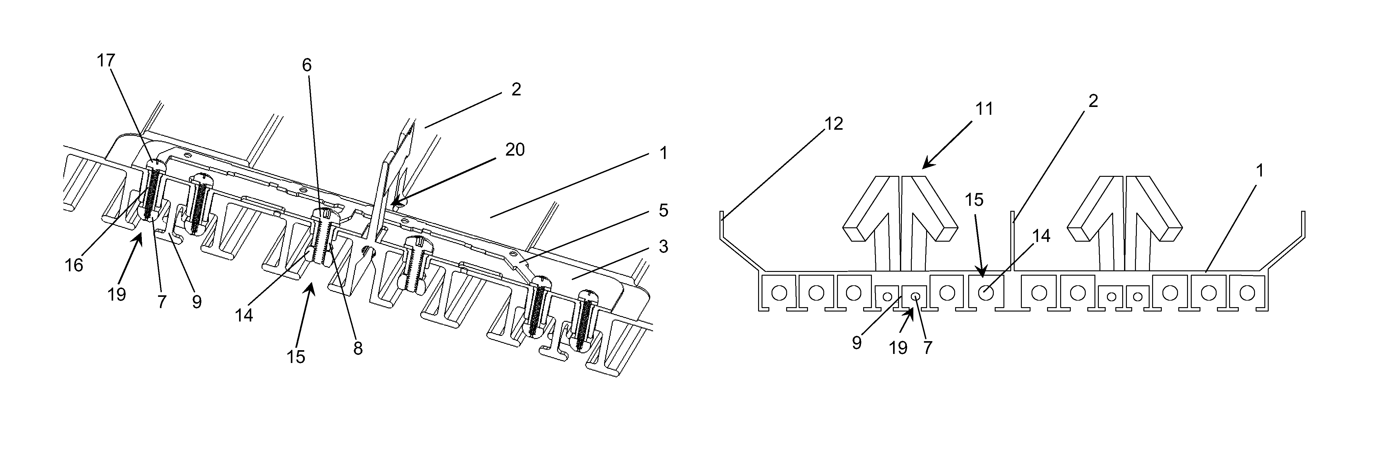
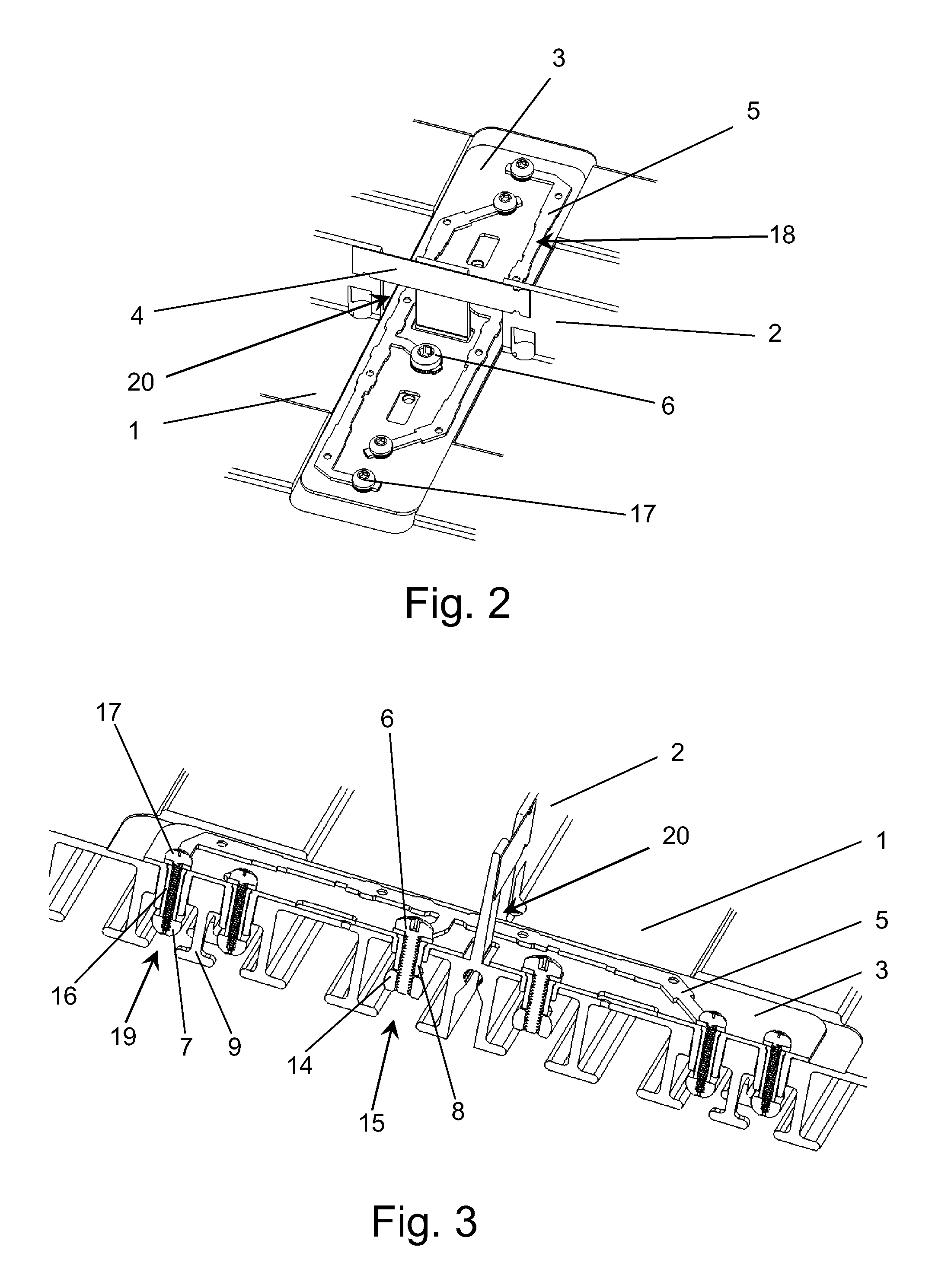
[0014]In FIGS. 2 and 3 is shown an embodiment of the microstrip line splitter / combiner arrangement 18 on the antenna reflector front side 1, but other embodiments with microstrip lines using other types of transmission lines could also be used.

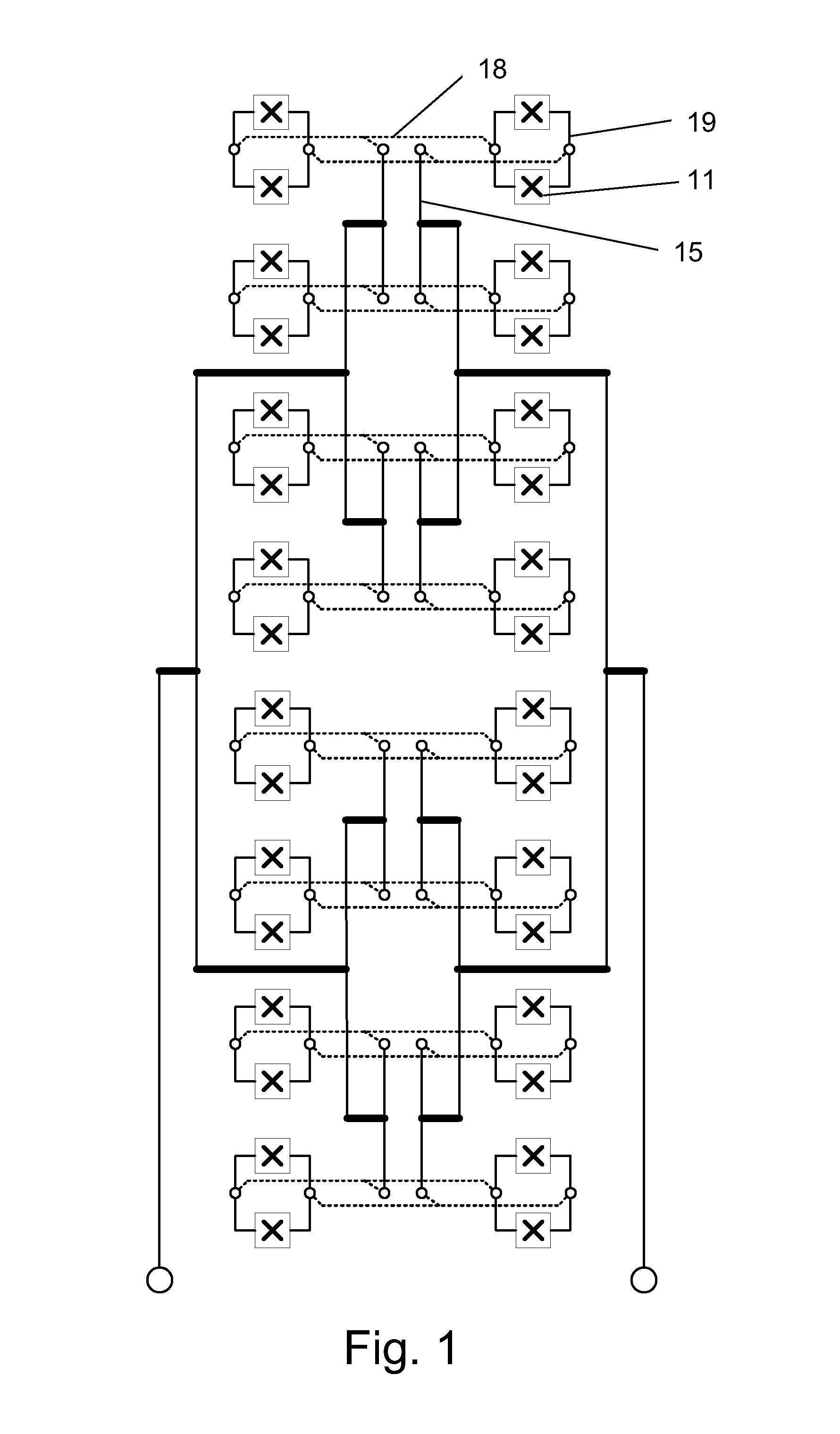
[0015]The microstrip line splitter / combiner comprises a conductor 5, a dielectric isolator 3 and a ground plane. In this embodiment, the reflector 1 acts as a ground plane. The microstrip line splitters / combiners 18 also split the signal so that it can feed the radiators 11 in each antenna column. The signal enters on the air coaxial line 15. It then passes through the reflector 1 using a conductive spacer 8 that connect the coaxial line 15 inner conductor 14 to the microstrip line splitter / combiner conductor 5. The signal is then split in two, and each signal again passes the reflector via other conductive spacers 16 to the inner conductor 7 of the coaxial lines 19 that are connected to the radiators 11. The screws 6 and 17 mechanically hold ...


PUM


Abstract

Antenna arrangement for a multi radiator base station antenna, the antenna having a feeding network based on air filled coaxial lines (15; 19), wherein the coaxial line being an integrated part of a back side of an antenna reflector (1), and wherein the coaxial line comprises an outer conductor (9) and an inner conductor (7; 14). Two parallel columns of radiators (11) are placed on a front side of the antenna reflector (1), the radiators (11) being fed from said feeding network.

Description

BACKGROUND OF THE INVENTION[0001]The present invention relates to an antenna arrangement for a multi radiator base station antenna, the antenna having a feeding network based on air filled coaxial lines, wherein the coaxial lines are an integrated part of the antenna reflector. The invention especially relates to such a dual polarised antenna having two parallel columns with dual polarised radiators.[0002]Antennas in telecommunication systems such as cellular networks today typically use multi-radiator structures. Such antennas make use of an internal feeding network that distributes the signal to the radiators from a common coaxial connector when the antenna is transmitting and in the opposite direction when the antenna is receiving. Typically radiators are positioned in a vertical column and radiators are fed via a feeding network from a common connector in a single polarisation antenna case, or fed via two feeding networks from two connectors in a dual polarisation case. This ver...

Claims


Application Information

Patent Timeline
IPC IPC(8): H01Q21/08H01Q21/26H01P1/18H01Q1/24
CPCH01Q1/246
Inventor JONSSON, STEFANKARLSSON, DAN
Owner CELLMAX TECH AB
Why Eureka
Try Eureka