Method and apparatus for isolation enhancement and pattern improvement of high frequency sub-arrays in dense multi-band omni directional small cell antennas

Pending Publication Date: 2022-04-07
COMM COMPONENTS ANTENNA INC
View PDF13 Cites 1 Cited by
  • Summary
  • Abstract
  • Description
  • Claims
  • Application Information

AI Technical Summary

Benefits of technology

The present invention is a new design of an antenna system that reduces the impact of lower frequency structures on the performance of higher frequency radiators. The antenna includes a multiband multiport MIMO omni directional antenna that improves elevation pattern and gain of higher frequency band arrays in the presence of lower frequency band arrays. The design uses interleaving of high band and higher band arrays horizontally on a single structure with waveguiding metal plates that make the lower band arrays almost invisible to higher band arrays. The diameter of the combined arrays is more than the diameter of two separate arrays, which reduces the negative impact of lower band structures on the high and mid band patterns. The technical effect of the new design is improved performance of higher frequency radiators in the presence of lower frequency structures.

Problems solved by technology

Design of omni-directional small cell base station antennas, confined to small volumes, having many ports, and operating at multiple of frequency bands, provides many technical hurdles.
The re-radiation of waves off of these surfaces add or exacerbate un-desired radiation patterns and can partially destroy the shape of the desired high frequency pattern.
Reducing this unwanted effect of the bulkier lower band radiators and reflectors on the performance of smaller radiator elements of the higher band arrays is a challenge.
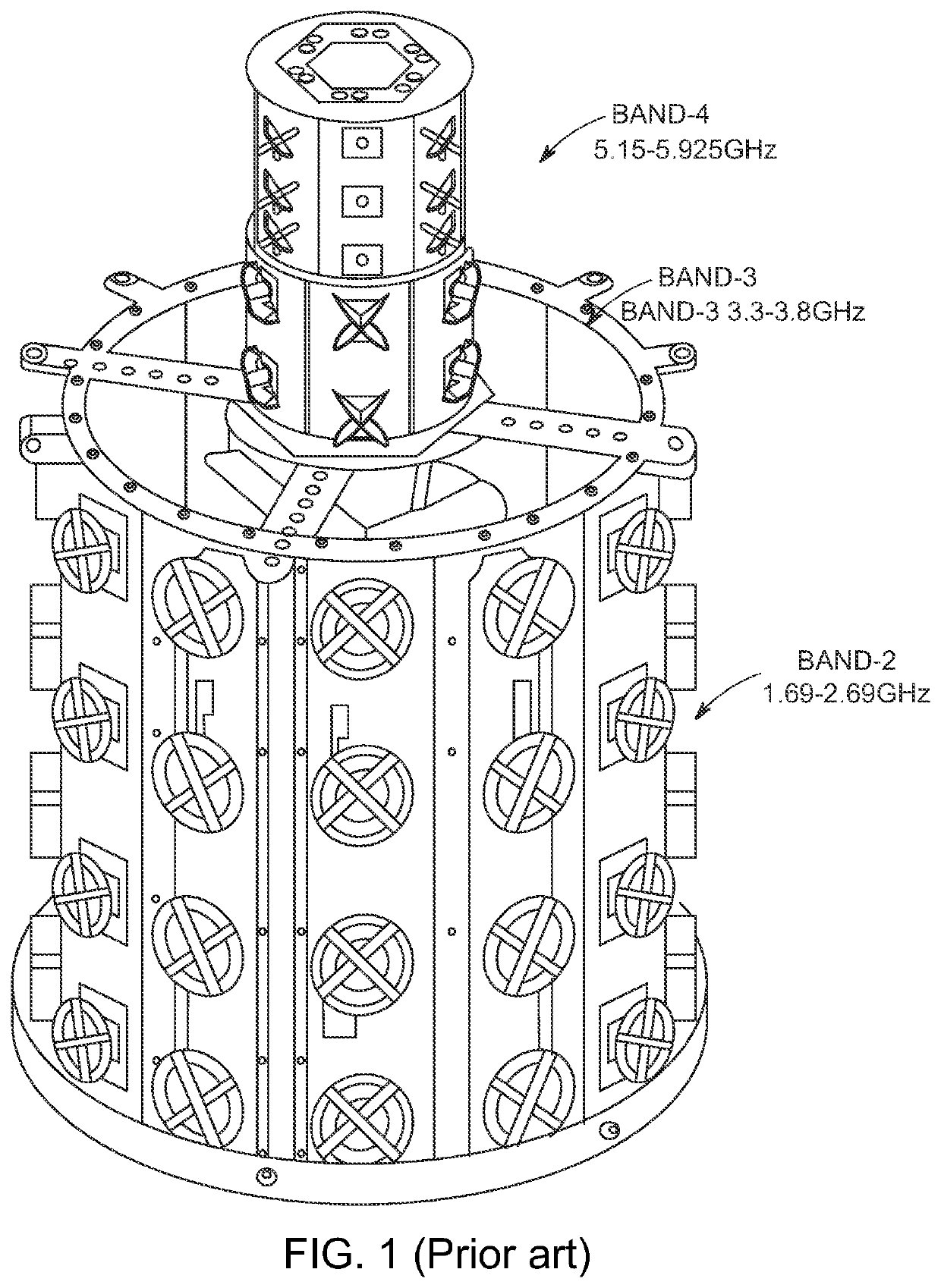
Normally, as shown in FIG. 1, the lower BAND-2 array on the bottom of the antenna, with its significantly larger lower band structures located below the bottom of the higher band, causes beam peak misalignment and upper sidelobe problems for the higher band arrays.
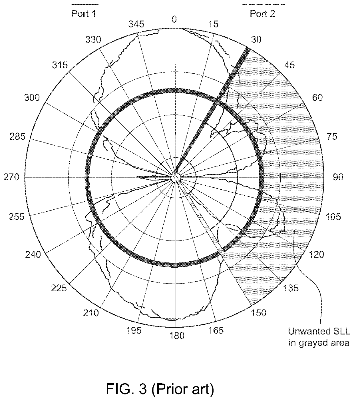
These SLL pattern issues are caused by higher frequency currents which are induced on reflectors and elements of lower band arrays.
Larger structures of the lower frequency band arrays cause more unwanted re-radiation as more current is induced on them, and small objects including the radiating elements themselves also have a resonance length in the band of interest and cause unwanted radiation.
These induced currents re-radiate and disturb the radiation pattern of the higher band arrays when they are tested in the full array in the presence of lower frequency arrays.
One prior art option to address this issue is to increase the spacing between higher and lower band arrays which can reduce the effect of spurious re-radiation of the higher bands from the low band reflectors and elements, but this solution is not possible for very dense arrays with limited height where there are no possibilities of introducing extra space between different band arrays.

Method used


Image

  • Method and apparatus for isolation enhancement and pattern improvement of high frequency sub-arrays in dense multi-band omni directional small cell antennas
  • Method and apparatus for isolation enhancement and pattern improvement of high frequency sub-arrays in dense multi-band omni directional small cell antennas
  • Method and apparatus for isolation enhancement and pattern improvement of high frequency sub-arrays in dense multi-band omni directional small cell antennas

Examples


Embodiment Construction

[0049]In one embodiment as shown in FIGS. 5A and 5B, an omni-directional small cell base station antenna 10 is shown with a lower structure 12 having spaced apart mid band reflectors 14, each with four mid band (BAND-2) dipole elements 16 forming a mid band (BAND-2) array 18. As shown in Both FIGS. 5A and 5B, antenna 10 also has an upper section 20 that has alternating high band (BAND-3) reflector plates 22 and very high band (BAND-4) reflector plates 24 each with high band (BAND-3) radiating elements 26 and very high band (BAND-4) radiating elements 28 respectively. Plates 22 and elements 26 form a high band (BAND-3) array 30 and plates 24 and elements 28 form a very high band (BAND-4) array 32. FIG. 5B is the close up of upper section 20 shown apart from lower structure 12.

[0050]As shown in FIG. 5B, for the combined high and very high band arrays 30 and 32 on upper portion 20 of antenna 10, reflector plates 22 and 24 are interspersed (every other plate) around the circumference in...


PUM


Abstract

An omni-directional small cell base station antenna includes at least one array of a first frequency on a lower portion of the antenna, at least one second array of a second frequency on an upper portion of the antenna, and at least one third array of a third frequency on the upper portion of the antenna. The second frequency is higher than the first frequency, and the third frequency is higher than the second frequency. The at least one second array at a second frequency includes a plurality of reflector plates with antenna elements of the second frequency thereon, and the at least one third array at a third frequency includes a plurality of reflector plates with antenna elements of the third frequency thereon. The reflector plates of the at least one second array are interspersed between the reflector plates of the at least one third array such that the reflector plates of the second and third arrays alternate around the circumference of the upper portion of the antenna.

Description

RELATED APPLICATION[0001]This application claims the benefit of priority from U.S. Provisional Application No. 63 / 074,328 filed on Sep. 3, 2020, the entirety of which is incorporated by reference.FIELD OF THE INVENTION[0002]The present invention relates to antennas for wireless communication. More particularly, the present invention relates to a multiport multiband quasi-omnidirectional antenna for small cell applications with improved patterns for mid and high band frequencies.PRIOR ART[0003]Design of omni-directional small cell base station antennas, confined to small volumes, having many ports, and operating at multiple of frequency bands, provides many technical hurdles. This is particularly true of designs for making these antennas as compact as possible without compromising signal integrity.[0004]Multiband MIMO (Multiple-In Multiple-Out) small cells among other technologies are used in 5G networks to provide increased capacity. Small cell networks can also help increase the ca...

Claims


Application Information

Patent Timeline
IPC IPC(8): H01Q5/30H01Q15/16H01Q1/24
CPCH01Q5/30H01Q1/246H01Q15/161H01Q5/307H01Q21/26H01Q21/205H01Q5/42H01Q1/523
Inventor HOJJAT, NASRINCLARKE, PAULBRIQUCH, ZOUHAIR
Owner COMM COMPONENTS ANTENNA INC
Why Eureka
Try Eureka