Automatic focusing apparatus and method

a technology of automatic focusing and focusing apparatus, which is applied in the direction of distance measurement, instruments, surveying and navigation, etc., can solve the problems of insufficient precision, higher cost, and higher complexity of assembly alignment, and achieve the effect of reducing the focusing tim

Active Publication Date: 2015-03-03
IND TECH RES INST
View PDF16 Cites 15 Cited by
  • Summary
  • Abstract
  • Description
  • Claims
  • Application Information

AI Technical Summary

Benefits of technology

[0007]The disclosure is directed to an automatic focusing apparatus a method thereof. The defocus position of the object is adjusted according to two imaging optical paths with different imaging precisions so as to reduce the focusing time.

Problems solved by technology

Conventional mechanical processing methods, being subjected to the blade size and mechanism restrictions, are found to be insufficient, and are gradually replaced by laser processing with higher precision and faster speed such as laser drilling and laser cutting.
The conventional automatic focusing method normally adapts the optical type automatic focusing apparatus, which has higher precision and is more expensive than the image type automatic focusing apparatus.
Thus, the optical type automatic focusing apparatus still has the problem of higher cost, larger volume and higher complexity in assembly alignment.
In addition, the larger the focusing times performed by optical type automatic focusing apparatus, the longer the processing time will be required, and this is disadvantageous to the reduction in production cost, and needs to be improved further.

Method used


Image

  • Automatic focusing apparatus and method
  • Automatic focusing apparatus and method
  • Automatic focusing apparatus and method

Examples


first embodiment

[0034]Referring to FIG. 4, an optical path of automatic focusing apparatus according to the first embodiment is shown. As indicated in FIG. 4, the automatic focusing apparatus includes a light source 100, an optical imaging unit 200, two photo-sensors 220 and 222 and a focusing regulation unit 300. In addition, the automatic focusing apparatus further uses a microscopic observation unit 400 for observing a real-time image, wherein the microscopic observation unit 400 includes an infinite optical path correction system 401 and an observation camera 402. The optical imaging unit 200 includes a beam shaping lens set 202, 203, a photo interrupter 204, multiple beam splitters 205, 206 and 208, an object lens 207, a first magnification adjustment lens 211 and a second magnification adjustment lens 221. The optical imaging unit 200 further divides the beam into a first imaging optical path L1 and a second imaging optical path L2 by the beam splitter 208. The first magnification adjustment ...

second embodiment

[0036]Referring to FIGS. 6 and 7. The first imaging optical path L1 and the second imaging optical path L2 can be disposed in the same manner as indicated in FIGS. 6 and 7. The optical path switch 229 and the optical path switch 228 can be movably disposed in the first imaging optical path L1 and the second imaging optical path L2 respectively that the reflecting beam B passes through before entering the photo-sensor 250.

[0037]As indicated in FIG. 6, after the reflecting beam B is divided into a first sub-beam B1 and a second sub-beam B2 by the beam splitter 208, the first sub-beam B1, having been focused by the first magnification adjustment lens 211 and reflected via a reflective lens 210, is not blocked by the optical path switch 229 and directly enter the beam splitter 260 and form an image on the photo-sensor 250, so that the photo-sensor 250 can detect the defocus position of the object S with the image. Moreover, the second sub-beam B2, having been focused by the second magni...

third embodiment

[0041]Referring to FIGS. 8 and 9. In the present embodiment, the photo-sensor can be realized by a single photo-sensor 250. The first imaging optical path L1 and the second imaging optical path L2 can be disposed in the same manner as indicated in FIGS. 8 and 9. The reflective lens 209 can be movably disposed in the optical path that the reflecting beam B passes through before entering the photo-sensor 250.

[0042]As indicated in FIG. 8, when the reflecting beam B is reflected via the reflective lens 209 and enters the first imaging optical path L1, the reflecting beam B, having been focused by the first magnification adjustment lens 211 and reflected via a reflective lens 210, directly enters the beam splitter 260 and forms an image on the photo-sensor 250, so that the photo-sensor 250 can detect the defocus position of the object S with the image.

[0043]As indicated in FIG. 9, when the reflective lens 209 is driven and shits its position, the reflecting beam B is not reflected via th...


PUM


Abstract

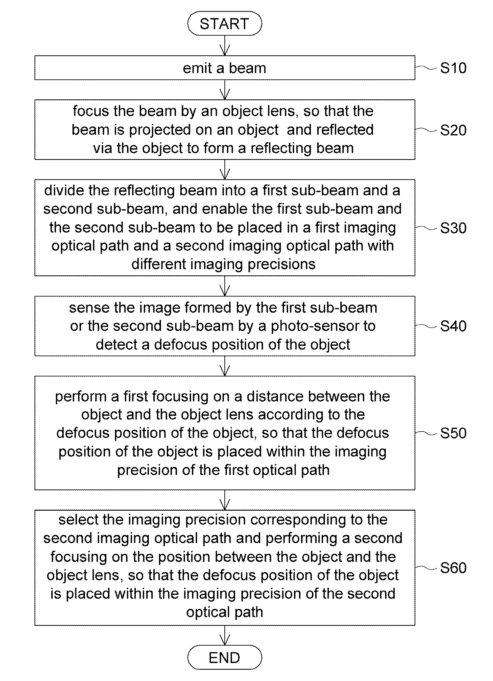
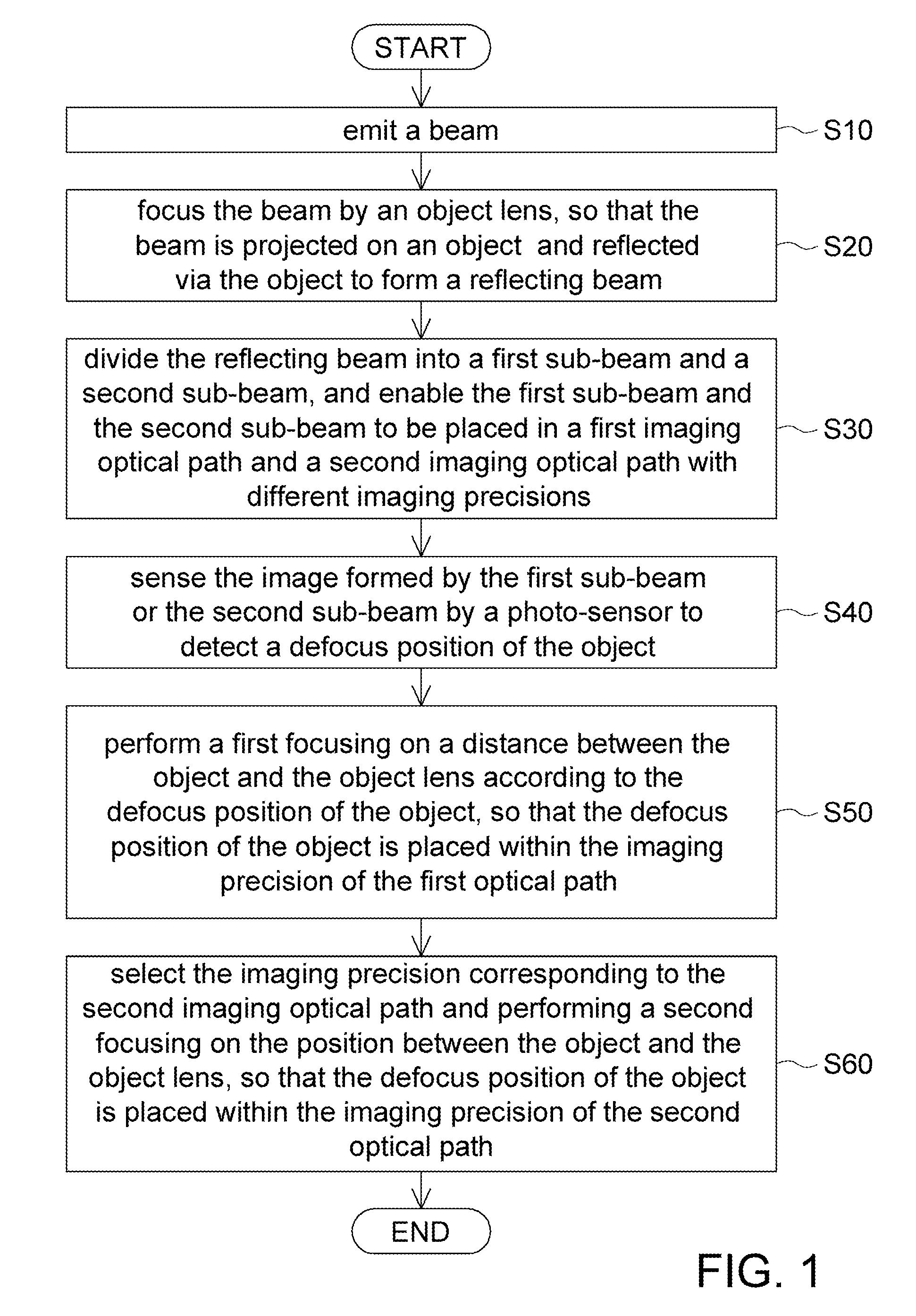
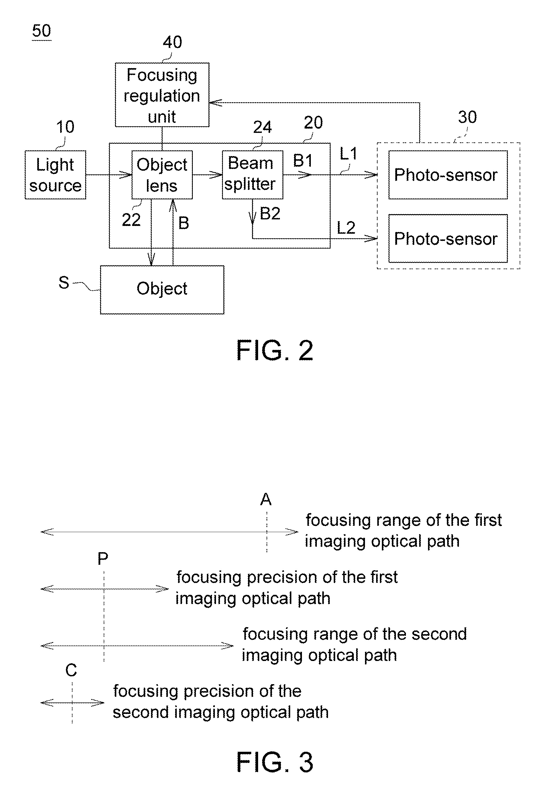
An automatic focusing apparatus and a method thereof are provided. The apparatus includes a light source, an optical imaging unit, a photo-sensor and a focusing regulation unit. The optical imaging unit includes an object lens and a beam splitter. The beam splitter divides a reflecting beam into a first sub-beam and a second sub-beam. The optical imaging unit has a first imaging optical path and a second imaging optical path with different imaging precisions corresponding to the first sub-beam and the second sub-beam, respectively. The photo-sensor detects a defocus position of the object. The focusing regulation unit adjusts the distance between the object and the object lens and selects an imaging precision, so that the defocus position of the object is placed within the imaging precision of the first optical path and the imaging precision of the second optical path in sequence.

Description

[0001]This application claims the benefit of Taiwan application Serial No. 99140848, filed Nov. 25, 2010, the subject matter of which is incorporated herein by reference.BACKGROUND[0002]1. Technical Field[0003]The disclosure relates in general to a focusing apparatus and method thereof, and more particularly to an automatic focusing apparatus automatically adjusting the imaging precision and a method thereof.[0004]2. Description of the Related Art[0005]As the electronic industry has gained booming growth in recent years, the miniaturization of consumer electronic products such as mobile phone, camera, and projector has become a mainstream trend in the market. In response to the needs of the electronic industry, the processing and formation methods of critical parts and assemblies are critical to the electronic industry. Conventional mechanical processing methods, being subjected to the blade size and mechanism restrictions, are found to be insufficient, and are gradually replaced by...

Claims


Application Information

Patent Timeline
Patent Type & Authority Patents(United States)
IPC IPC(8): G01C3/08G02B7/28G02B21/24G02B27/16G03B30/00
CPCG02B27/16G02B7/36G02B21/245
Inventor LIU, CHIEN-SHENGHU, PIN-HAO
Owner IND TECH RES INST
Why Eureka
Try Eureka