Camera module and auto focusing method of camera module

a camera module and camera technology, applied in the field of camera modules and auto focusing methods of camera modules, can solve the problems of consuming a lot of current, wasting a lot of time for auto focusing, and a large number of manual focusing time, and achieve the effect of shortening the auto focusing tim

Inactive Publication Date: 2013-07-04
LG INNOTEK CO LTD
View PDF5 Cites 11 Cited by
  • Summary
  • Abstract
  • Description
  • Claims
  • Application Information

AI Technical Summary

Benefits of technology

[0015]The VCM according to the present disclosure has an advantageous effect in that a displacement of a rotor is determined depending on posture of a VCM having a bi-directionally driven rotor, and...

Problems solved by technology

A conventional super small digital camera used on a mobile phone has suffered from a disadvantage of disablement to adjust a gap between a lens and an image sensor changing an outside light to a digital image or a digital video (moving image).
However, the rotor according to the conventional bi-directionally driven VCM is disadvantageous ...

Method used


Image

  • Camera module and auto focusing method of camera module
  • Camera module and auto focusing method of camera module
  • Camera module and auto focusing method of camera module

Examples


first exemplary embodiment

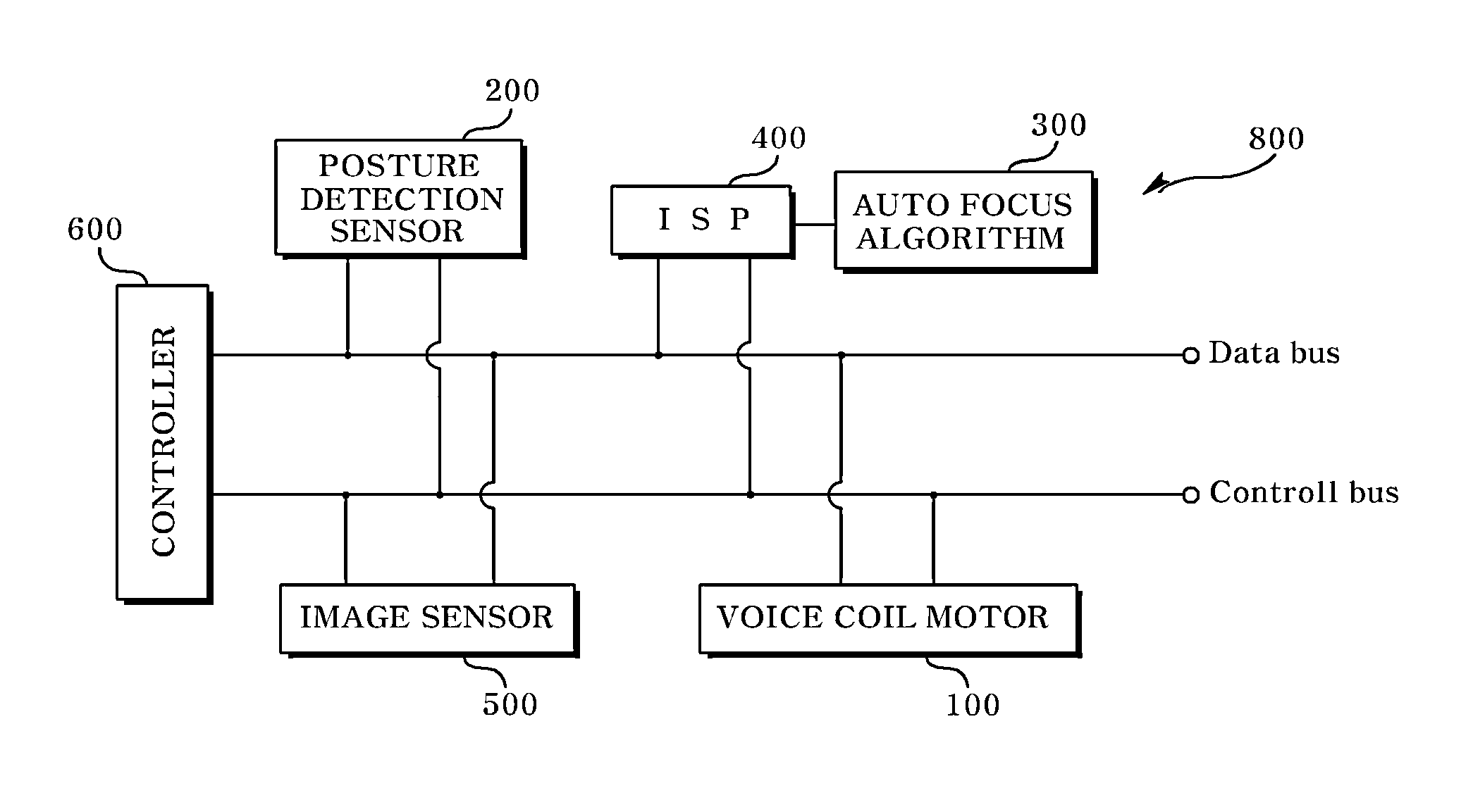
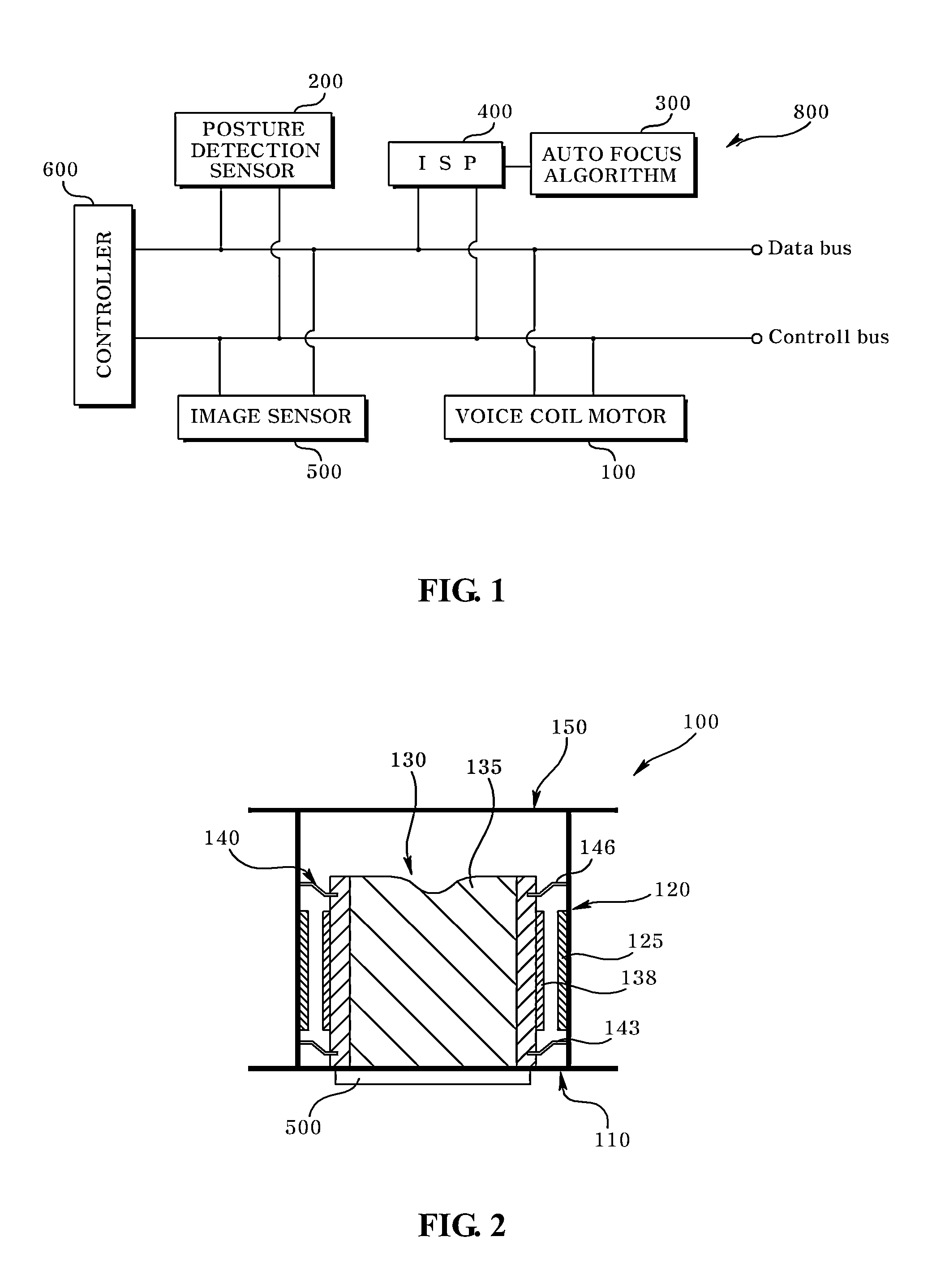
[0035]FIG. 1 is a block diagram illustrating a camera module according to a first exemplary embodiment of the present disclosure, and FIG. 2 is a schematic cross-sectional view illustrating a VCM of FIG. 1.

[0036]Referring to FIGS. 1 and 2, a camera module (800) includes a VCM (Voice Coil Motor, 100) driven to one direction, a posture detection sensor (200), an auto focus algorithm (300), an ISP (Image Signal Processor, 400), an image sensor (500) and a controller (600).

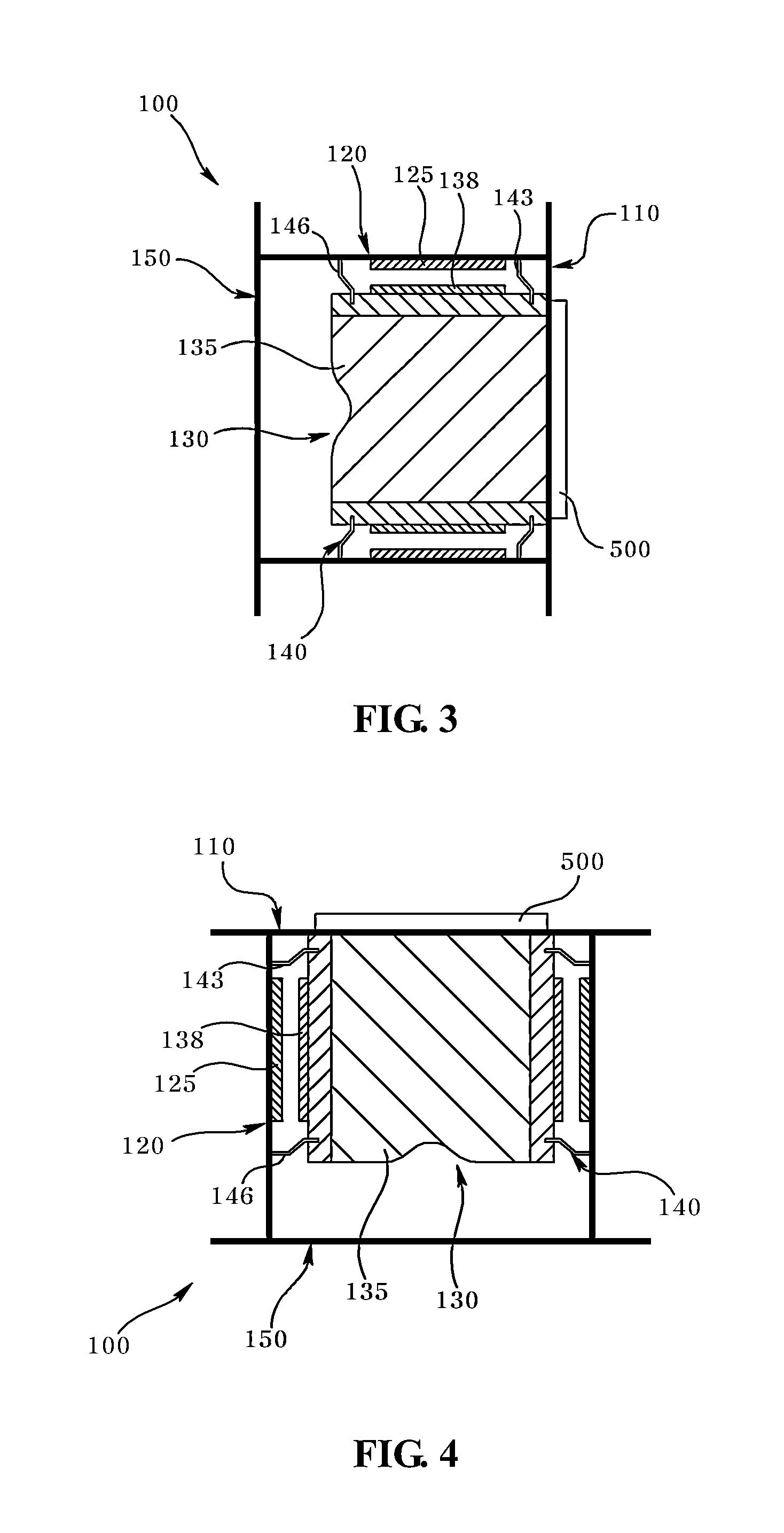
[0037]Referring to FIG. 2, the VCM (100) performs an auto focusing operation by driving a lens to one direction. That is, a lens mounted on the VCM (100) is moved to a direction ascending from a base (110, described later), and performs the auto focusing operation between the lens and the image sensor (500) during the moving process. The VCM (100) includes a base (110), a stator (120), a rotor (130), an elastic member (140) and a cover (150).

[0038]The base takes a shape of a plate centrally formed with an opening pass...

second exemplary embodiment

[0078]FIG. 10 is a flowchart illustrating an auto focusing method of a camera module according to a second exemplary embodiment of the present disclosure.

[0079]Referring to FIGS. 1 and 10, a step of determining what posture is currently taken by the VCM (100) is implemented in order to perform the auto focusing of the camera module (S10). The posture of the VCM (100) may be realized by the posture detection sensor (200) such as a gyro sensor.

[0080]The posture detection sensor (200) outputs mutually different sensing signals in response to the postures of the VCM (100), e.g., the ‘up’ posture, the ‘side’ posture and the ‘down’ posture of the VCM (100). In a case the posture of the VCM (100) is determined by the posture detection sensor (200), the auto focus algorithm (300) applies an initial driving signal to contact the rotor (130) to an upper surface of the base (110) (S15).

[0081]In a case the rotor (130) is contacted to an upper surface of the base (110), a ‘non-driving section’ a...

third exemplary embodiment

[0100]FIG. 14 is a flowchart illustrating an auto focusing method of a camera module according to a third exemplary embodiment of the present disclosure.

[0101]To be more specific, referring to FIGS. 1 and 14, in order to implement the auto focusing operation, in a case a driving current is not applied from the camera module, a posture of the rotor (130) contacted to the base (100) by the elastic member (140), which is a reference plane, is first determined by using a position detection sensor such as a gyro sensor (S40).

[0102]Successively, an initial driving current is applied to the rotor (130) in order to implement the auto focusing operation to cause the rotor (130) to be arranged an upper surface of the base (110) (S45).

[0103]Thereafter, one auto focus algorithm is selected from a plurality of auto focus algorithms formed in number corresponding to that of the postures of the rotor (130) of the VCM (100) (S50). The auto focus algorithm may include a first auto focus algorithm co...


PUM


Abstract

A camera module and an auto focusing method of the camera module are provided, the camera module including a VCM (Voice Coil Motor) including a rotor including a lens distanced from a reference plane, in a case no driving signal is applied, a posture detection sensor determining a posture of the VCM; an ISP (Image Signal Processor) generating a driving signal for driving the VCM using an optimum focus value of the lens calculated by an auto focus algorithm in response to a posture of the VCM determined by the posture detection sensor, an image sensor changing lens-passed light to a digital signal, and a controller controlling the VCM, the posture detection sensor, the image signal processor and the image sensor.

Description

CROSS-REFERENCE TO RELATED APPLICATIONS[0001]This application claims the benefit under 35 U.S.C. §119 of Korean Patent Application Nos. 10-2011-0145806, filed Dec. 29, 2011, and 10-2011-0145807, filed Dec. 29, 2011, which are hereby incorporated by reference in their entirety.BACKGROUND[0002]1. Field of the invention[0003]The present disclosure relates to a camera module configured to be driven to one direction or to a bi-direction, and an auto focusing method of a camera module.[0004]2. Description of Related Art[0005]Recently, a mobile phone embedded with a super small digital camera and a tablet PC has been developed. A conventional super small digital camera used on a mobile phone has suffered from a disadvantage of disablement to adjust a gap between a lens and an image sensor changing an outside light to a digital image or a digital video (moving image). However, recently, a lens driving device, such as a VCM (Voice Coil Motor) capable of adjusting a gap between an image senso...

Claims


Application Information

Patent Timeline
IPC IPC(8): H04N5/232
CPCH04N5/232H04N5/23212H04N5/2257H04N23/57H04N23/67G02B7/09G02B7/28G03B13/36
Inventor PARK, SANG OKLEE, SEONG MIN
Owner LG INNOTEK CO LTD
Why Eureka
Try Eureka