Delivery assembly for occlusion device using mechanical interlocking coupling mechanism

a technology of mechanical interlocking coupling and delivery assembly, which is applied in the field of delivery assembly to achieve the effect of accurate and rapid deployment of the occlusion device at the target location

Active Publication Date: 2015-03-10
ACHIEVA MEDICAL
View PDF11 Cites 9 Cited by
  • Summary
  • Abstract
  • Description
  • Claims
  • Application Information

AI Technical Summary

Benefits of technology

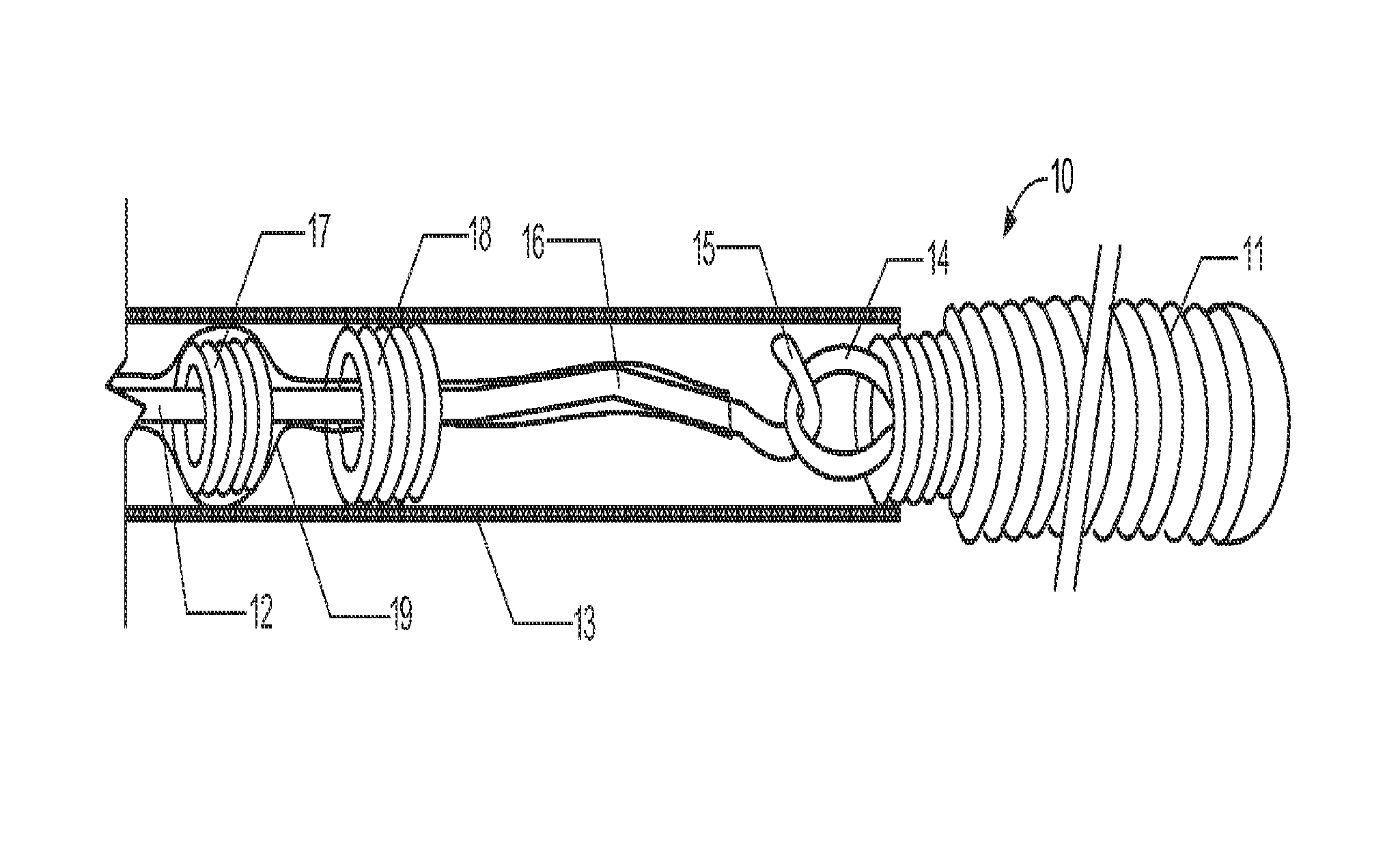
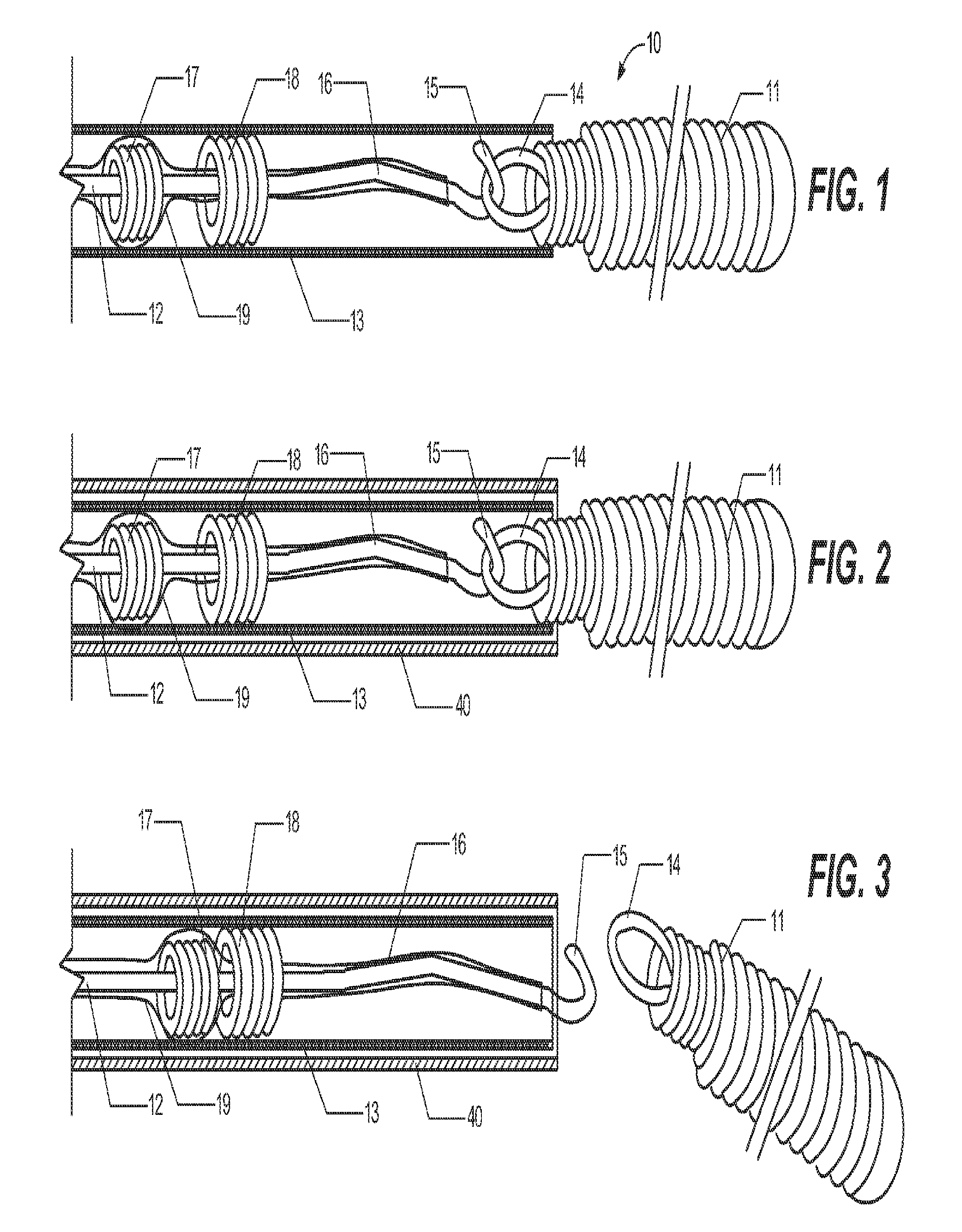
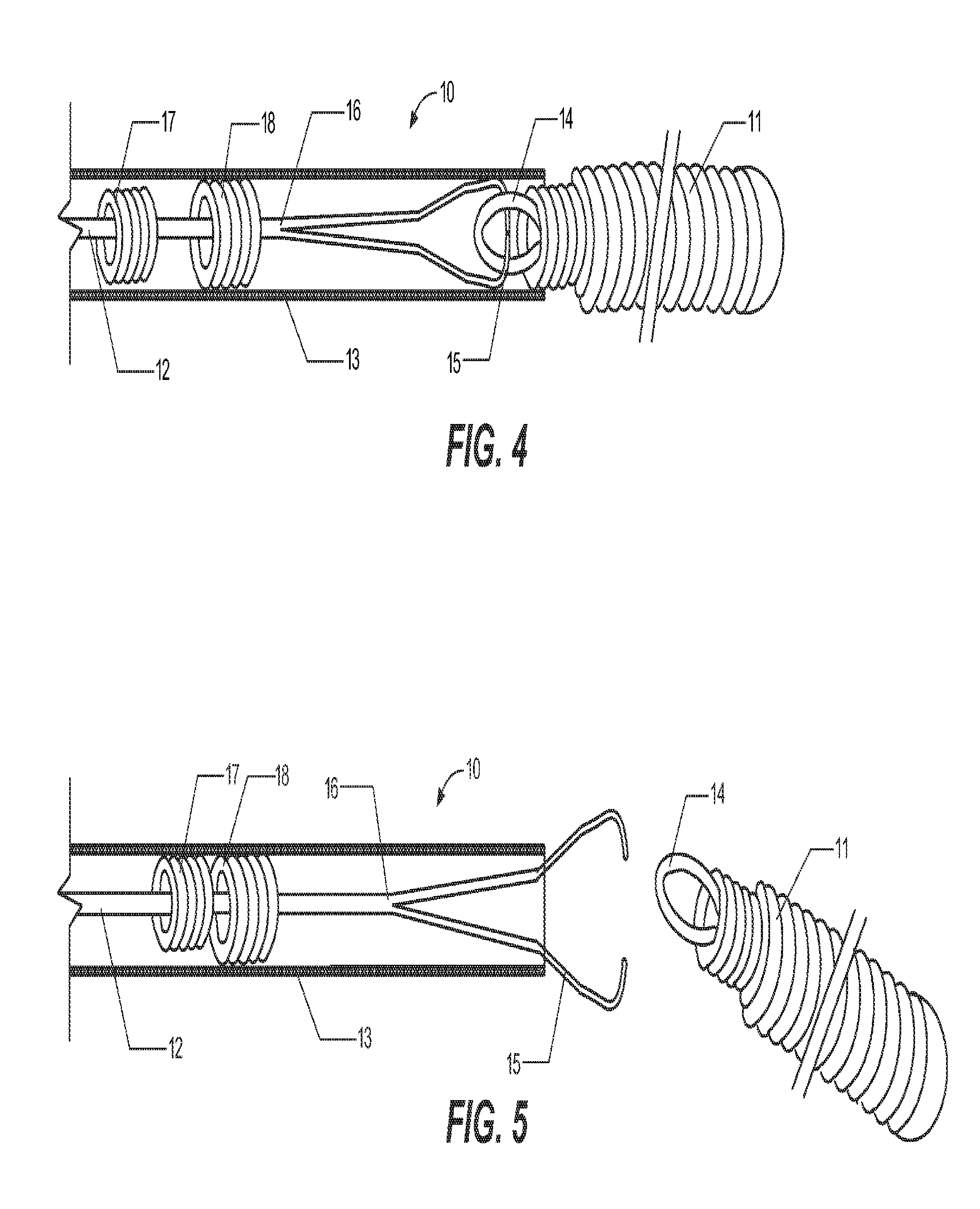
[0014]Briefly, and in general terms, the present invention presents a delivery assembly and methods for accurately and rapidly deploying an occlusion device at a target location within a patient. Preferably, the target location is within a patient's vasculature. The delivery assembly comprises an occlusive implant device that is an occlusive coil, a pushwire for pushing and deploying the occlusive coil through an elongated and flexible delivery sleeve, a first member of an interlocking mechanism, the first member being located at the distal end of the pushwire, and a second member of an interlocking mechanism, the second member being located at the proximal end of the occlusive coil. Optionally, the delivery assembly comprises a pushwire locking device located at the proximal end of the pushwire to prevent any relative movement between the pushwire and the delivery sleeve during delivery procedure. Optionally, two markers are attached to the delivery assembly in a configuration that allows for advancement of the pushwire through a delivery sleeve to the target site, but that contact each other to prevent over-extending of the pushwire / occlusive coil into the aneurysm. Preferably, the distal portion of the pushwire is coated with PTFE (Polytetrafluoroethylene) to provide a lubricous surface to aid the catheter in moving in the artery.
[0015]In one embodiment of the present invention, the occlusive coil is attached to the distal end of the pushwire of the delivery assembly through interlocking mechanism. The pushwire can be a tapered wire, tapered at its distal end to enhance pushability of said pushwire and to enhance trackability of the attached occlusive coil. In a preferred aspect of this embodiment, the interlocking mechanism comprises a first locking member and a second locking member. Preferably, said first locking member is a hook and said second locking member is a loop. Alternatively, said first locking member is a loop and said second locking member is a hook. The hook member is preferably a J-shaped hook, though alternative shapes such as Y-shapes, S-shapes and the like are useful.
[0017]Further, the invention advantageously incorporates a two marker system to enhance the precision of the deployment of the occlusive device to the target site. For this two marker system, there are attached markers to each of the pushwire and the delivery sleeve individually. Each of these markers may be made of a radiopaque material selected from platinum, gold, tungsten, rhenium, palladium, rhodium, and alloys thereof, or any combination thereof. The presence of two markers serves several purposes: First, a radiopaque marker is visible under radiographic conditions, thereby allowing the physician to identify the position of both the pushwire and the delivery sleeve to determine their relative positions within the microcatheter. Second, during deployment of the occlusive coil at the point when the interlocking joint is being pushed out from the delivery sleeve, the proximal marker, which is fixed onto the pushwire, will be pushed forward but will be blocked by the distal marker which is fixedly attached onto the inner surface of the delivery sleeve. This blocking prevents any further advancement of the pushwire into the aneurysm and prevents over-deployment of the pushwire into the target location. Using these radiopaque markers in such a configuration allows the occlusive coil to be precisely placed inside the aneurysm while also operating to prevent over-extending of the pushwire causing further injury to the aneurysm. Hence the two markers system acts as a safety catch to prevent over-extending of the pushwire.
[0021]Another aspect of the invention is that the delivery sleeve is made of polymeric material comprising one or more of, Polyimide, polyether block amide, nylon, PTFE (Polytetrafluoroethylene), Polyetheretherketone (PEEK) and block copolymers thereof. Further, the delivery sleeve can be formed of two or more materials. For example, a proximal section of the delivery sleeve can be made of a first material and the distal section from a second material. A proximal section made of a polymide and a distal section made of nylon is a more specific example, though is provided only for illustration and not limitation. Additionally, the delivery sleeve can further comprise a reinforced wire to become braided tubing so to enhance the kink-resistance of the delivery sleeve. Alternatively, the surface of the delivery sleeve can further comprise of a layer of hydrophilic coating to enhance the trackability of the delivery assembly, which can be many different types of well-known hydrophilic polymer such as polyvinyl compounds, polyurethanes, polyacrylates or copolymers of vinyl compounds and acrylates or anhydrides, especially polyethyleneoxide, polyvinylpyrrolidone, and polyurethane. In a further alternative the lumen of said delivery sleeve can comprise a PTFE liner. Preferably, said PTFE liner provides a lubricated inner surface that facilitates navigation of a pushwire and occlusive device through said lumen of said delivery sleeve.

Problems solved by technology

Second, during deployment of the occlusive coil at the point when the interlocking joint is being pushed out from the delivery sleeve, the proximal marker, which is fixed onto the pushwire, will be pushed forward but will be blocked by the distal marker which is fixedly attached onto the inner surface of the delivery sleeve.

Method used


Image

  • Delivery assembly for occlusion device using mechanical interlocking coupling mechanism
  • Delivery assembly for occlusion device using mechanical interlocking coupling mechanism
  • Delivery assembly for occlusion device using mechanical interlocking coupling mechanism

Examples


Embodiment Construction

[0034]Referring to the drawings introduced in the previous section, several embodiments of a delivery assembly are shown according to the principles of the present invention. However, the disclosed embodiments are merely exemplary of the invention which may be embodied in various forms. Details disclosed herein merely as a basis for claims and for teaching one skilled in the art to employ the present invention in any appropriate manner.

[0035]FIG. 1 illustrates a preferred embodiment of the pusher-occlusive coil assembly of present invention. The delivery assembly, generally designated as 10, comprises an occlusive coil 11 and a tapered pushwire 12 that is engaged with the occlusive coil 11 through interlocking mechanism 14 and 15. Said delivery assembly 10 can be confined inside the lumen of an elongated flexible delivery sleeve 13 which can be inserted into the vasculature of a patient for delivery of said occlusive coil 11 to a target site.

[0036]The interlocking mechanism comprise...


PUM


Abstract

A pusher-occlusive coil delivery assembly 10 that is advanced through a microcatheter 40 to the desired vascular site within a patient. The delivery assembly 10 includes a pushwire 12 which interlocks with the occlusive coil 11 which can be manipulated to detach the occlusive coil 11. When the assembly 10 is positioned at the site, the pushwire 12 is advanced to allow the interlock joint 14, 15 to move out of the delivery sleeve 13 to uncouple the pushwire 12 and the occlusive coil 11.

Description

PRIORITY DOCUMENTS[0001]This Application claims the benefit of U.S. provisional patent application Ser. No. 61 / 170,991, filed Apr. 20, 2009, which is incorporated herein by reference.FIELD OF THE INVENTION[0002]The present invention is related to a medical device and its use for delivery to a target site to create an intra-vascular embolism within the patient. More particularly, the invention relates to a delivery assembly, comprising a pushwire and an occlusive coil, wherein the pushwire and occlusive coil are releasably connected by a unique, mechanically interlocking configuration.BACKGROUND[0003]The use of an interventional apparatus such as a microcatheter assembly for placing occlusive devices, such as embolic coils, stents and dilation balloons, at target sites throughout the body have become standard procedures for endovascular disease treatment. Such approach is particularly useful in treating diseases that are located where traditional operational procedures pose a greater...

Claims


Application Information

Patent Timeline
Patent Type & Authority Patents(United States)
IPC IPC(8): A61M29/00A61B17/00A61B17/12A61B19/00
CPCA61B17/12113A61B17/1214A61B19/54A61B2017/00867A61B2017/12054A61B90/39
Inventor TAN, JIANFONGZHANG, PING YE
Owner ACHIEVA MEDICAL
Why Eureka
Try Eureka