Chemically based vascular occlusion device deployment

a vascular occlusion device and chemical technology, applied in the field of chemical based vascular occlusion device deployment, can solve the problems of coil over shoot, coil cannot be retracted, and may migrate to an undesired location, etc., to achieve accurate and rapid deployment of vascular occlusion devices

Inactive Publication Date: 2010-08-24
CODMAN & SHURTLEFF INC
View PDF51 Cites 6 Cited by
  • Summary
  • Abstract
  • Description
  • Claims
  • Application Information

AI Technical Summary

Benefits of technology

[0009]The present invention embodies a deployment system and method for accurately and rapidly deploying a vascular occlusion device at a preselected site within the vasculature of a patient. The deployment system may employ an elongated flexible delivery catheter for guiding a deployment unit to the preselected site. The deployment unit includes a delivery tube or pusher that pushes and guides the vascular occlusion device, such as an embolic coil, through the delivery catheter to the preselected site.

Problems solved by technology

Due to the delicate tissue surrounding cranial blood vessels, especially for example brain tissue, it is very difficult and often risky to perform surgical procedures to treat such a defect.
Some of the problems that have been associated with these procedures relate to the accuracy of coil placement.
For example, the force of the coil exiting the delivery catheter may cause the coil to over shoot the predetermined site or dislodge previously deployed coils.
Also, once the coil is pushed out of the distal end of the catheter, the coil cannot be retracted and may migrate to an undesired location.
Often, retrieving and repositioning the coil requires a separate procedure and has the potential to expose the patient to additional risk.
One drawback to using this type of system is the potential risk of melted adhesives contaminating the blood stream.
One drawback is that connecting the resistance heating coil to the power source requires running multiple wires through the pusher member.
Additionally, the electrical current traveling through the wires may create stray electromagnetic fields that interfere with other surgical and monitoring equipment.
This type of ball and socket connection is rigid and causes the catheter to be stiff, making it difficult to guide the catheter through the vasculature of the body.
If the electronic equipment is defective or the power source fails, for example a battery pack fails, the procedure may be prolonged while the equipment is repaired or replaced.
Prolonging the procedure may expose the patient to additional risk.

Method used


Image

  • Chemically based vascular occlusion device deployment
  • Chemically based vascular occlusion device deployment
  • Chemically based vascular occlusion device deployment

Examples


Embodiment Construction

[0022]As required, detailed embodiments of the present invention are disclosed herein; however, it is to be understood that the disclosed embodiments are merely exemplary of the invention, which may be embodied in various forms. Therefore, specific details disclosed herein are not to be interpreted as limiting, but merely as a basis for the claims and as a representative basis for teaching one skilled in the art to variously employ the present invention in virtually any appropriate manner.

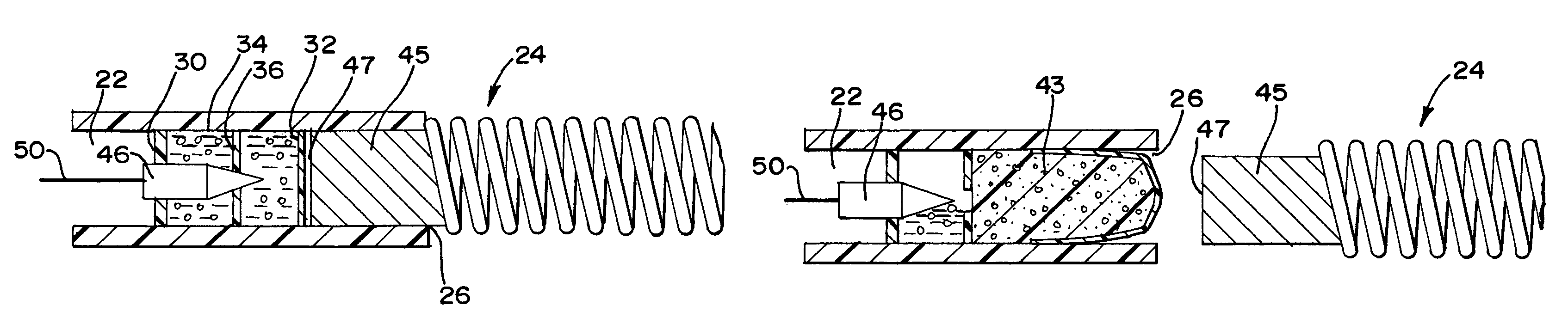
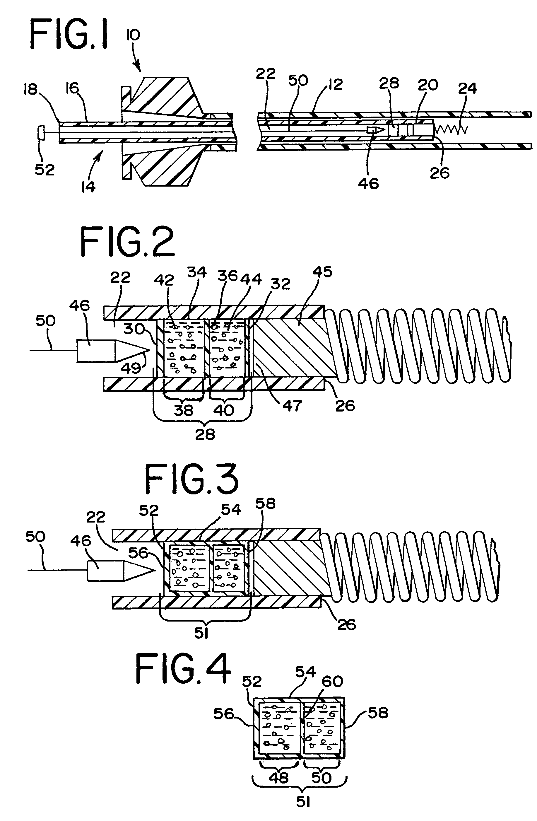
[0023]FIG. 1 generally illustrates a preferred embodiment of the vascular occlusion device deployment system of the present invention. The deployment system, generally designated at 10, includes an elongated flexible guiding catheter 12 which is inserted into the vasculature of a patient and used to guide a deployment unit, generally designed 14, to a preselected site in a manner generally known in the art. The deployment system 14 includes an elongated flexible pusher or delivery tube 16 having a ...


PUM


Abstract

A vascular occlusion device deployment system for placing an occlusion device at a preselected site within the vasculature of a patient. The deployment system employing a pusher having a lumen with an opening at the distal end of the pusher. A vascular occlusion device is connected to the distal end of the pusher by a portion that is removeably disposed within the opening. The portion of the occlusion device is forced out of the opening by an expandable reaction chamber, thereby deploying the occlusion device.

Description

FIELD OF THE INVENTION[0001]The present invention is related to deployment systems and methods for accurately and rapidly deploying vascular occlusion devices at a preselected location within the vascular system of a patient, and more particularly, deployment approaches that utilize an expanding chemical reaction chamber to facilitate rapid deployment of vascular occlusion devices.BACKGROUND OF THE INVENTION[0002]The use of catheter delivery systems for positioning and deploying therapeutic devices, such as dilation balloons, stents and embolic coils, in the vasculature of the human body has become a standard procedure for treating endovascular diseases. It has been found that such devices are particularly useful in treating areas where traditional operational procedures are impossible or pose a great risk to the patient, for example in the treatment of aneurysms in cranial blood vessels. Due to the delicate tissue surrounding cranial blood vessels, especially for example brain tiss...

Claims


Application Information

Patent Timeline
Patent Type & Authority Patents(United States)
IPC IPC(8): A61M29/00
CPCA61B17/1214A61B17/12109A61B17/12022A61B2017/12081
Inventor JONES, DONALD K.MITELBERG, VLADIMIR
Owner CODMAN & SHURTLEFF INC
Why Eureka
Try Eureka