
Elevated gun sighting device for hitting moving targets

a sighting device and moving target technology, applied in the field of shotgun sighting devices, can solve the problems of difficult to navigate through the field of indicators and lines in order to make a logical choice for the first shot, and the likelihood of missing the target is much higher. , to achieve the effect of fast and easy removal from the gun barrel

Active Publication Date: 2015-03-17
RILEY JIMMY PATRICK
View PDF15 Cites 9 Cited by
  • Summary
  • Abstract
  • Description
  • Claims
  • Application Information

AI Technical Summary

Benefits of technology

This patent describes a small and easy-to-use gun sighting device that is perfect for hitting moving targets like wing hunting and target shooting. It can be quickly and easily attached and removed from most shotguns, and it helps the shooter align their aim and target with greater precision. This device can also act as a rear sight, allowing the shooter to use additional targeting markings on the sight.

Problems solved by technology

Despite the method of sighting, missing the target is much more likely than hitting the target.
One of the challenges associated with the shooting of moving targets such as game birds for example, are the constantly changing variables such as the bird's speed, distance, altitude, angle of flight and even the size of bird itself.
Another critical issue that confronts the shooter on every shot is their ability to level the gun barrel onto the flight path of the moving target.
The first problematic issue with prior art is their use of complex lines and angled indicators that the shooter must navigate through before they can acquire a firing solution.
Considering that most shooters would only have a few seconds, it would be very difficult to navigate through the field of indicators and lines in order to make a logical choice for the first shot.
Any subsequent shots would even be more problematic.
The second problematic issue is the reliance on target size as the means of selecting the appropriate target indicator.
Considering that most targets are extremely small from the shooters vantage point, it would be difficult for the shooter to make split second decisions based on target size.
The third problematic issue is the use of the existing gun barrel sight as the primary gun sight for the device.
Attaching and surrounding the existing gun sight with additional devices only exacerbates the difficulty of sighting and leveling the gun barrel while using the existing gun barrel sight.

Method used


Image

  • Elevated gun sighting device for hitting moving targets
  • Elevated gun sighting device for hitting moving targets
  • Elevated gun sighting device for hitting moving targets

Examples


Embodiment Construction

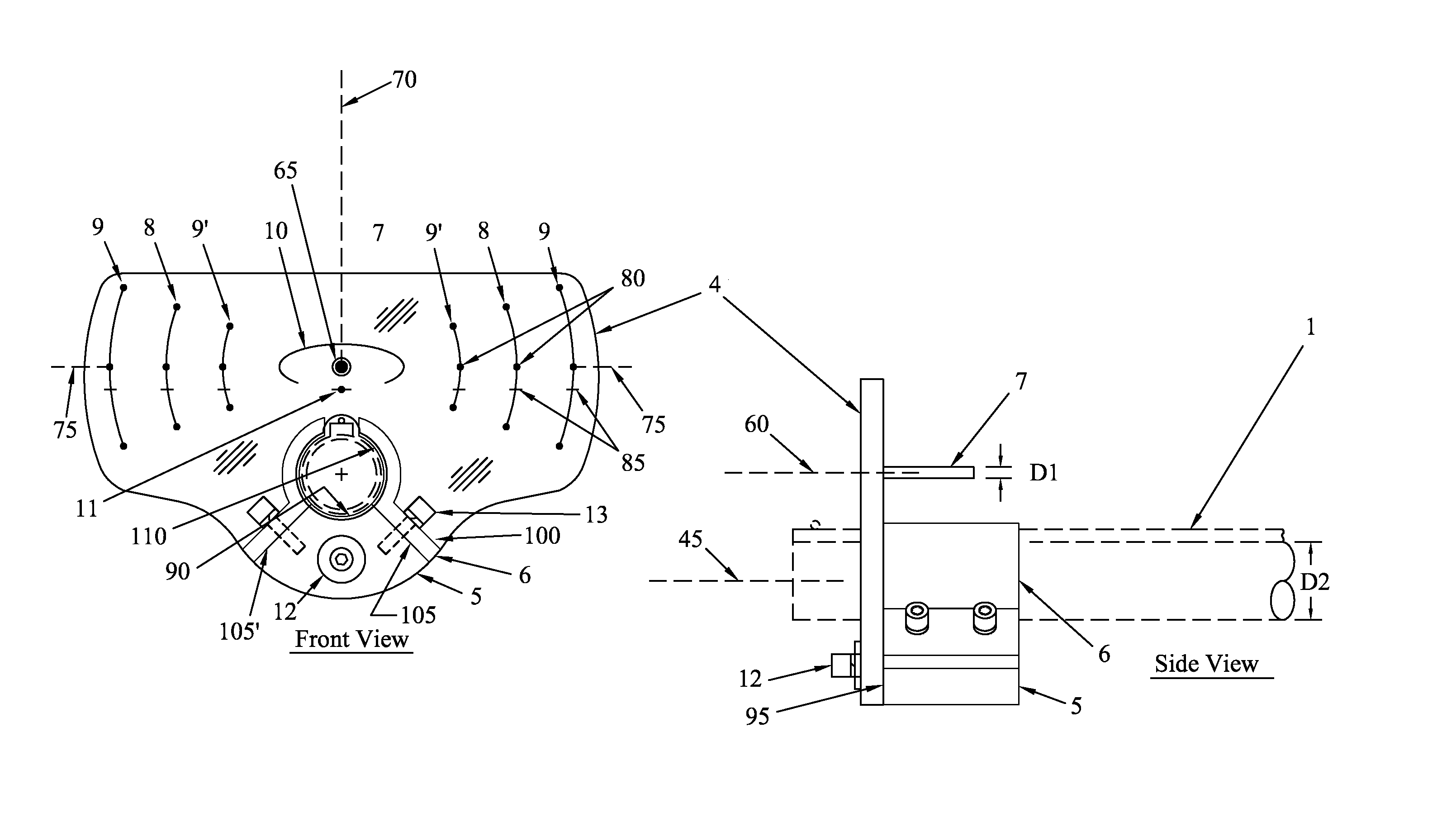
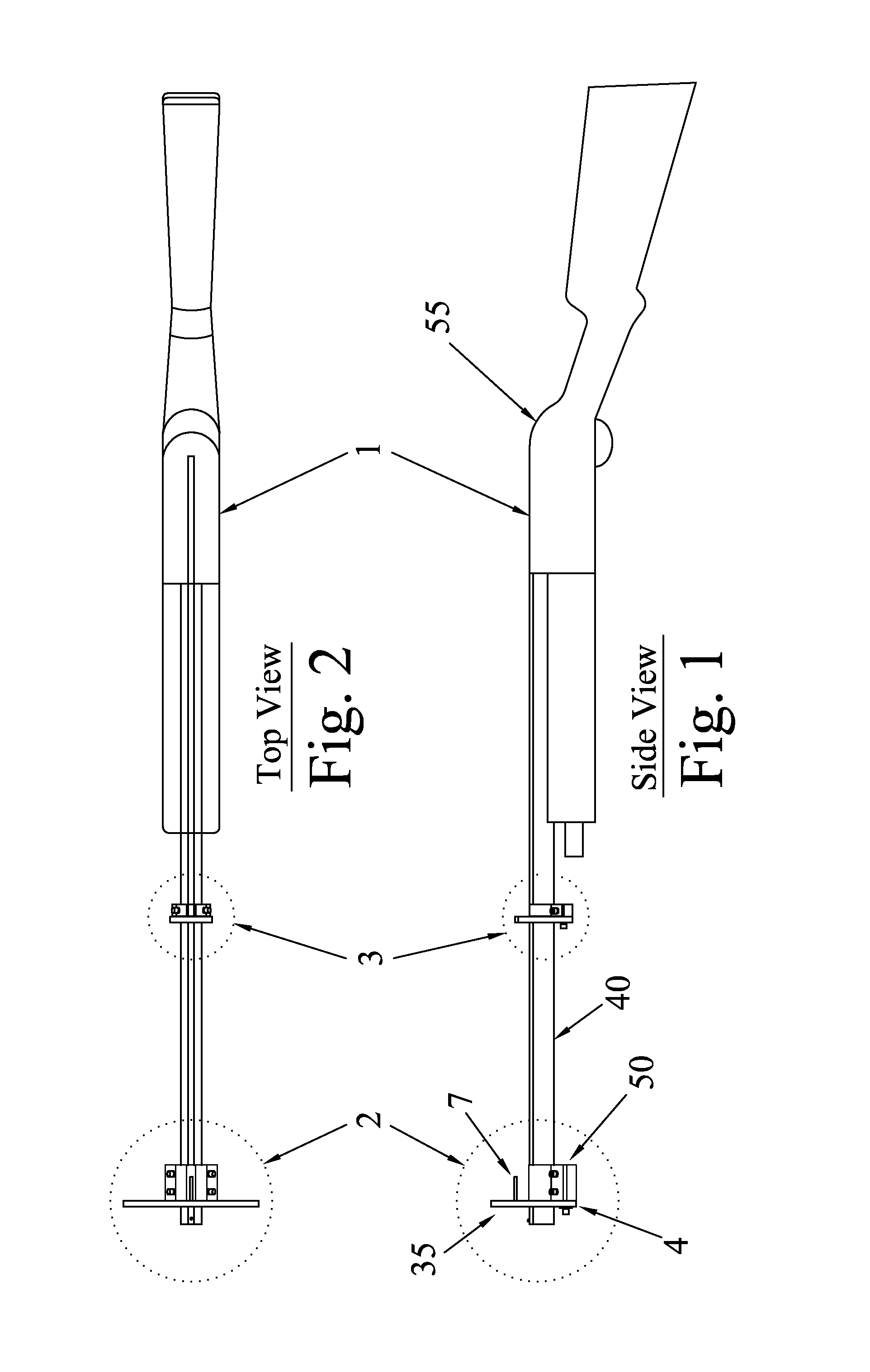
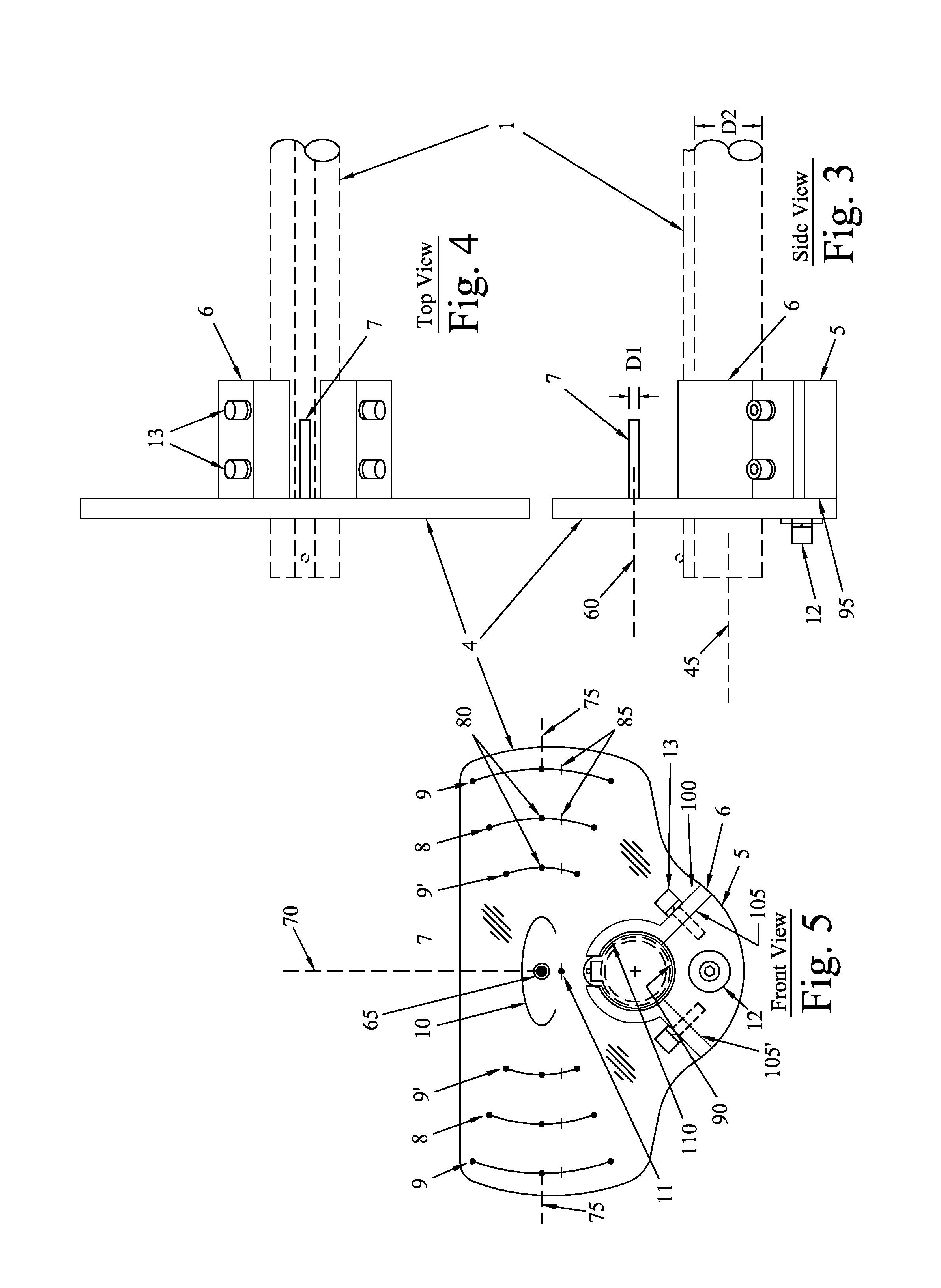
[0048]One embodiment of the invention provides a shotgun sight 35 comprising a clear plate 4, a pin 7 and a mounting means 50. The pin extends generally normally from the plate and has a first diameter and a longitudinal axis. The mounting means is attached to the plate for mounting the plate to a shotgun 55 comprising a barrel 40 having a second diameter. See FIG. 1. The barrel has a longitudinal axis 45 positioned parallel to the longitudinal axis 60 of the pin. See FIG. 3.

[0049]Generally speaking, the second diameter will be in the range of 3 to 30 times larger than the first diameter, usually in the range of 5 to 15 times larger than the first diameter.

[0050]The longitudinal axis of the pin is generally positioned at a distance in the range of 1 to 3 times the second diameter from the longitudinal axis of the shotgun barrel. In the case of a single barrel shotgun, (see FIG. 3, for example) the longitudinal axis of the pin is generally positioned at a distance in the range of 1 t...


PUM


Abstract

A shotgun sight for mounting to the end of a shotgun barrel comprises a clear plate having a pin extending generally normally from the plate back toward the eye of the shooter and parallel to the axis of the barrel. The plate has a circle surrounding the base of the pin to facilitate proper eye positioning for use of the plate as a sighting device and a dot marked on the plate between the pin and the barrel to serve as an elevation mark. Arcs marked on the plate centered on the pin serve as lead indicators for moving targets.

Description

CROSS REFERENCES TO RELATED APPLICATIONS[0001]This application claims the benefit of U.S. Provisional Application No. 61 / 763,855 filed 12 Feb. 2013, the disclosure of which is incorporated by reference herein.FIELD OF THE INVENTION[0002]In one aspect, the invention relates to a sighting device for a shotgun. In another aspect, the invention relates to a non-optical, non-electronic shotgun sight for hitting moving targets.BACKGROUND OF THE INVENTION[0003]Hunters and target shooters alike have always been intrigued by the challenge of wing hunting and target shooting using moving targets. Some shooters will tell you that they simply point the gun ahead of the target and do not sight with one eye closed while others will tell you just the opposite that they actually do sight with one eye closed. Despite the method of sighting, missing the target is much more likely than hitting the target.[0004]One of the challenges associated with the shooting of moving targets such as game birds for ...

Claims


Application Information

Patent Timeline
IPC IPC(8): F41G1/473
CPCF41G1/473F41G11/004F41G1/02
Inventor RILEY, JIMMY PATRICK
Owner RILEY JIMMY PATRICK
Learn More