Small diameter pressure structure commercial aircraft crew rest

a pressure structure and small diameter technology, applied in the direction of aircraft crew accommodation, seating arrangements, transportation and packaging, etc., can solve the problems of limiting the capacity of the aircraft for carrying cargo or passengers, affecting the flight, and affecting the flight. , to achieve the effect of expanding the usable common area floor spa

Active Publication Date: 2015-03-31
BE INTPROP
View PDF24 Cites 21 Cited by
  • Summary
  • Abstract
  • Description
  • Claims
  • Application Information

AI Technical Summary

Benefits of technology

[0011]In another presently preferred aspect, the crew rest station includes an emergency escape hatch, and a fold-down jump seat typically adjacent to the emergency escape hatch. In another presently preferred aspect, the crew rest station includes a fold-down entry door that removably covers a stairwell or ladder area of the central vestibule, to expand the usable common area floor space of the crew rest station.

Problems solved by technology

However, such facilities have been more uncommon for long distance airline flights, due to aircraft weight constraints and limitations of available space aboard aircraft.
However, the crew rest facility is located in the lower lobe cargo bay of the aircraft, and occupies otherwise valuable cargo space, resulting in a loss of full freight capability for the aircraft.
The weight of the crew rest facility is approximately 2,200 pounds, which further limits the capacity of the aircraft for carrying cargo or passengers.

Method used


Image

  • Small diameter pressure structure commercial aircraft crew rest
  • Small diameter pressure structure commercial aircraft crew rest
  • Small diameter pressure structure commercial aircraft crew rest

Examples


Embodiment Construction

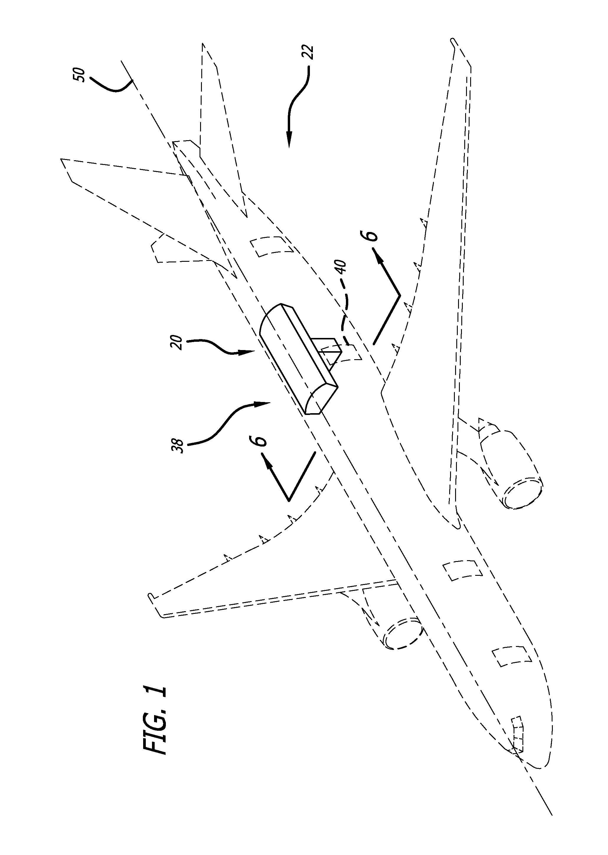
[0026]As is illustrated in the drawings, the invention is embodied in an improved aircraft crew rest station for an aircraft used for long distance flights. More particularly with reference to FIGS. 1 and 6, in a presently preferred embodiment, the present invention provides an improved crew rest station 20 for an aircraft 22, such as the Airbus A330 / A340 for example, having a hull 24 with a curved top portion 26, a lowered ceiling 28, and a space 30 therebetween, typically provided for overhead stowage bins 32, and various types of ducting 34 above a passenger seating area 36. The aircraft crew rest station is typically located approximately in the aircraft midsection 38, adjacent door number three 40, and attached to the airframe of the aircraft.

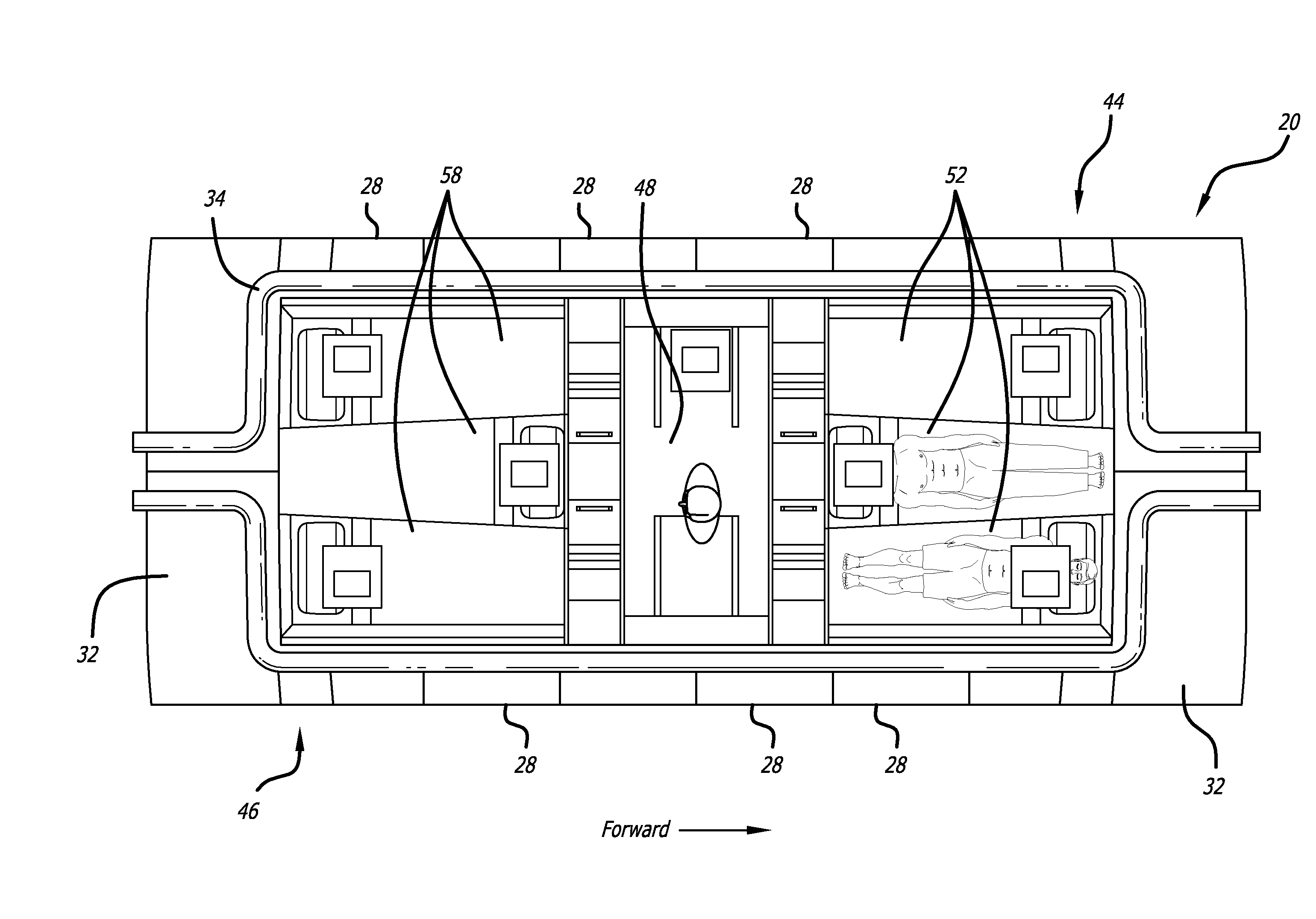
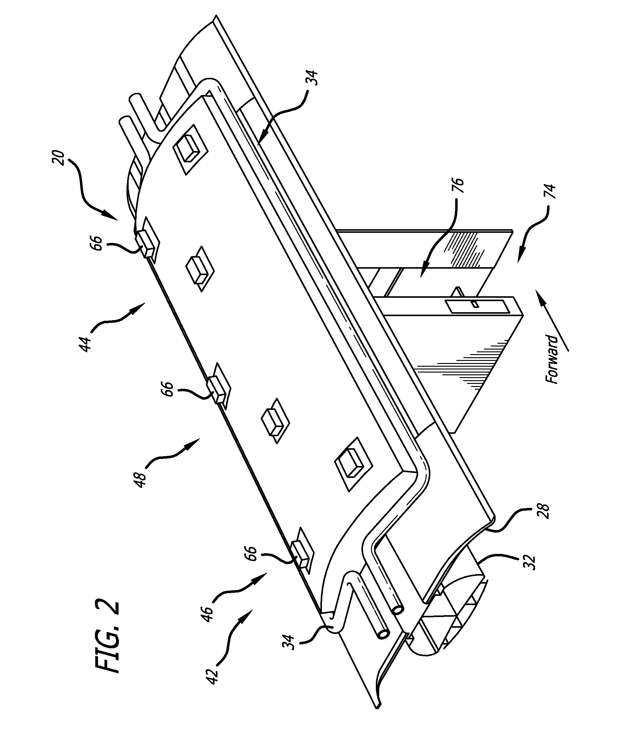
[0027]Referring to FIGS. 2-5 and 11, the crew rest station includes an overhead crew rest portion 42 with a forward bunk portion 44, an aft bunk portion 46, and a central deck portion 48. Each of the forward and aft bunk portions extends f...


PUM


Abstract

An aircraft crew rest station includes an overhead crew rest portion including a central deck portion, forward and aft bunk portions, and a central entry vestibule connected between a passenger seating area and the central deck portion. The forward and aft bunk portions include a plurality of adjacent partitioned individual sleeping berths configured in interfitting alternating trapezoid shapes to optimize spatial accommodation of body proportions of crew members in the available aircraft space. The central deck portion includes an emergency escape hatch, a fold-down jump seat, and a fold-down entry door that removably covers a stairway of the central entry vestibule.

Description

CROSS-REFERENCES TO RELATED APPLICATIONS[0001]This application is based upon and claims priority from U.S. Provisional Application No. 61 / 286,344, filed Dec. 14, 2009, which is incorporated by reference in its entirety.BACKGROUND[0002]This invention relates generally to resting and sleeping quarters for an aircraft crew, and more particularly concerns overhead aircraft crew resting and sleeping quarters in a space-saving and weight-saving configuration occupying substantially otherwise unused space aboard an aircraft.[0003]Resting or sleeping facilities are commonly provided for the crew and passengers of ships, boats, trucks, buses, and the like when they are used for transportation of cargo or passengers over long distances. For example, one conventional arrangement for a two-deck trailer includes upper deck and lower deck sections, with the upper deck section including beds and stairs leading from one end of the lower deck to a central area of the upper deck. However, such facili...

Claims


Application Information

Patent Timeline
Patent Type & Authority Patents(United States)
IPC IPC(8): B64D11/00
CPCB64D11/00B64D2011/0076Y02T50/46Y02T50/40
Inventor PAPKE, ROBERT
Owner BE INTPROP
Why Eureka
Try Eureka