Method and system for display calibration with feedback determined by a camera device

a camera device and calibration method technology, applied in the field of system and method for display calibration, can solve the problems of dire consequences in the production environment, repair and/or recalibration can be very expensive, and achieve the effect of efficient recalibration and accurate display managemen

Active Publication Date: 2015-03-31
DOLBY LAB LICENSING CORP
View PDF29 Cites 8 Cited by
  • Summary
  • Abstract
  • Description
  • Claims
  • Application Information

AI Technical Summary

Benefits of technology

[0022]To perform contrast calibration in accordance with some embodiments, a camera (or handheld) device senses the image displayed by the display device in response to a checkerboard test pattern that is non-uniform (in the sense that the size of its individual fields varies with spatial position in the displayed image), to determine local (intra-frame) contrast as a function of spatial position in the displayed image. In some embodiments, a processor of the camera (or handheld) device recognizes location within the displayed image by recognizing a feature size associated with each location, and determines contrast at each of one or more locations. The resolution (feature size) at which the fields of uniform checkerboard pattern become flat (i.e., the minimum resolvable displayed feature size of the test pattern's features) can readily and efficiently be determined.
[0026]In order to recalibrate the display device to match its settings as determined in the preliminary display characterizing operation, the previously determined display output values fD(λ) are provided (e.g., downloaded over the internet) to the camera device. Using the measured f′D(λ) values, the provided fc(λ) and fD(λ) values, and the determined f′c(λ) values, the camera device determines f″D(λ)=(fc(λ) / f′c(λ))*(f′D(λ), for each of the wavelengths, which is the display response function (at the initial) that would have been measured using the calibrated reference camera rather than the camera device's camera. The f″D(λ) values are used (e.g., sent to a remote server) to recalibrate the display. In some embodiments, the camera device determines difference values dD(λ)=f″D(λ)−fD(λ), using the determined f″D(λ) values and the provided f′D(λ) values, for each of the wavelengths. The values dD(λ) are indicative of the difference between the display response function at the initial time and at the time of the preliminary characterizing operation. The difference values dD(λ) values may be used (e.g., sent to a remote server) to efficiently recalibrate the display to match its settings at the time of the preliminary characterizing operation.
[0028]In some embodiments, the camera device determines difference values dD(λ)=(fc(λ) / f′c(λ))*(f″D(λ)−f′D(λ)), using the measured f″D(λ) values and the stored fc(λ), f′c(λ), and f′D(λ) values, for each of the wavelengths. The function dD(λ) is the difference between the display response function at the time T1 and the display response function at the initial time, that would have been measured using the calibrated reference camera rather than the camera device's camera. The difference values dD(λ) values may be used (e.g., sent to a remote server) to efficiently recalibrate the display to match its settings at the initial time.
[0029]For a particular camera device (for example, a handheld camera device), it is contemplated that reference data indicative of color matching and / or color response functions (e.g., the above-mentioned reference camera sensitivity function fc(λ), and display response fD(λ)) for a particular display can be packaged (e.g., by the manufacturer) into a file readable by the camera device. In order to recalibrate the color or contrast of a display, a user could load the reference data and appropriate application software into a camera device. While executing the software, the camera device would make necessary measurements of light emitted by the display, and compare them against corresponding values of the reference data for the measured display, and preferably also determine difference values indicative of the differences between the measured values and corresponding reference data values. For example, at a time T1, using reference data indicative of a reference camera sensitivity function fc(λ), and display response fD(λ) previously generated using the reference camera, the camera device could determine values f′c(λ)=f′D(λ) / (fD(λ) / fc(λ)) indicative of the sensitivity function of the camera device's camera, and values indicative of display response function f′″D(λ)=(fc(λ) / f′c(λ))*(f″D(λ)), which is the display response function at the time T1 that would have been measured using the reference camera used to generate the previously determined display response fD(λ), where f″D(λ) is the display response function at the time T1 measured using the camera device's camera). The camera device could then compute difference values ΔD(λ)=(f′″D(λ)−fD(λ)), for each of a set of measured wavelengths. The difference values (indicative of changes in characteristics of the display since its original calibration using the reference camera) would then be used to recalibrate the display (e.g., the difference values are sent to a remote server which generates preprocessor control parameters in response thereto, and sends the preprocessor control parameters to a video preprocessor which uses them to recalibrate the display). More generally, the difference values can be used for one or more of the following operations: auto-recalibration of a display; and feedback preprocessing of input image data (to be displayed by a display) for accurate display management.

Problems solved by technology

An off-calibrated display can lead to dire consequences in the production environment and repair and / or recalibration can be very expensive.

Method used


Image

  • Method and system for display calibration with feedback determined by a camera device
  • Method and system for display calibration with feedback determined by a camera device
  • Method and system for display calibration with feedback determined by a camera device

Examples


Embodiment Construction

[0044]Many embodiments of the present invention are technologically possible. It will be apparent to those of ordinary skill in the art from the present disclosure how to implement them. Embodiments of the inventive system and method will be described with reference to FIGS. 1-3.

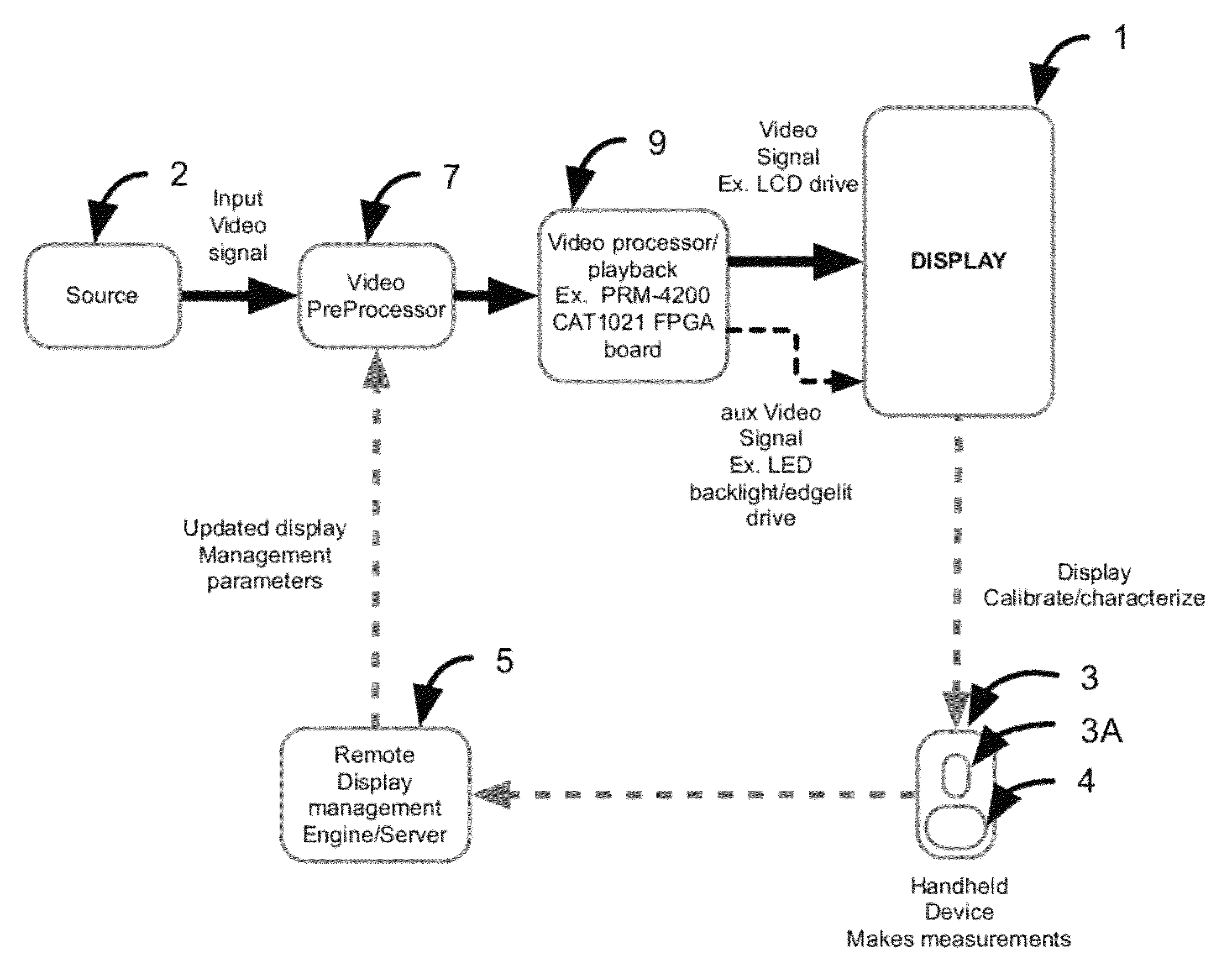
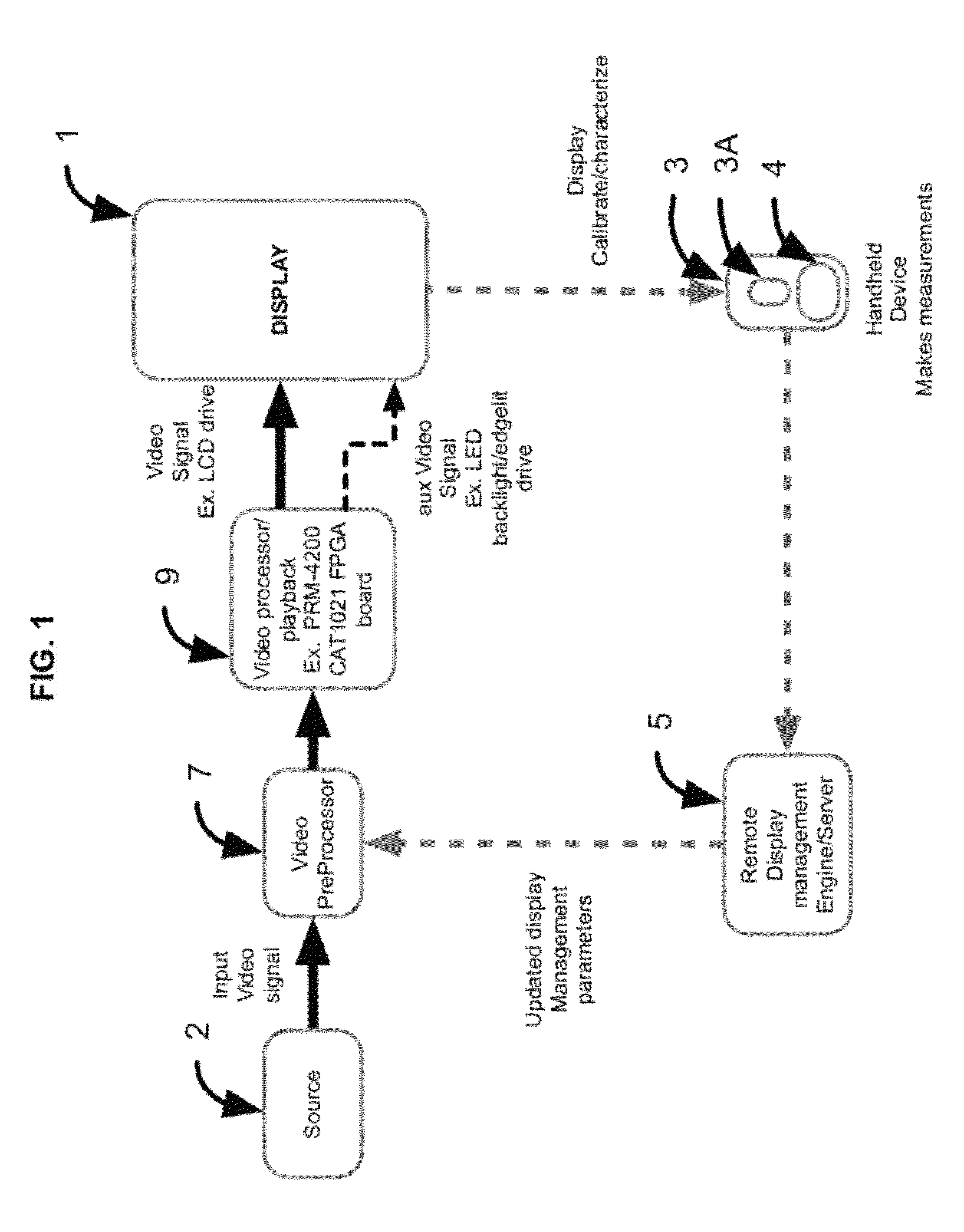
[0045]FIG. 1 is a block diagram of an embodiment of the inventive system. The system of FIG. 1 includes display device 1 configured to display images sequentially in response to a video input signal from source 2. Display device 1 may be implemented as any of a variety of display devices, (e.g., a standard LCD display, a high contrast LCD display, or another display device). For example, in a class of implementations, device 1 is an LED or LCD display including a front panel (comprising an array of LCD or LED pixels) and a backlighting (or edge-lighting) system for illuminating the pixels of the front panel. A backlighting system typically includes a backlight panel comprising an array of individually contro...


PUM


Abstract

In a class of embodiments, a method and system for calibrating a display using feedback indicative of measurements of light, emitted from the display (typically during display of a test pattern), by a camera device whose camera has a sensitivity function that is unknown a priori but which is operable to measure light emitted by a display in a manner emulating at least one measurement by a reference camera having a known sensitivity function. Typically, the camera device is a handheld camera device including an inexpensive, uncalibrated camera. In another class of embodiments, a system including a display (to be recalibrated), a video preprocessor coupled to the display, and a feedback subsystem including a camera device operable to measure light emitted by the display. The feedback subsystem is coupled and configured to generate preprocessor control parameters in response to measurement data (indicative of measurements by the camera device) and to assert the preprocessor control parameters as calibration feedback to the preprocessor. The preprocessor is operable to calibrate (e.g., recalibrate) the display in response to the control parameters by filtering input image data (e.g., input video data) to be displayed, for example to automatically and dynamically correct for variations in calibration of the display.

Description

BACKGROUND OF THE INVENTION[0001]1. Field of the Invention[0002]Some embodiments of the invention are systems and methods for calibrating a display using a camera device (e.g., a handheld camera device) to measure light emitted by the display in a manner emulating measurements by a reference camera having known sensitivity function but without preknowledge of the sensitivity function of the camera device's camera. In typical embodiments, preprocessor control parameters determined using a handheld or camera device are asserted as feedback to a video preprocessor to recalibrate a display.[0003]2. Background of the Invention[0004]Throughout this disclosure including in the claims, the expression performing an operation “on” signals or data (e.g., filtering or scaling the signals or data) is used in a broad sense to denote performing the operation directly on the signals or data, or on processed versions of the signals or data (e.g., on versions of the signals that have undergone prelim...

Claims


Application Information

Patent Timeline
Patent Type & Authority Patents(United States)
IPC IPC(8): G09G5/00G09G3/20
CPCG09G3/20G09G2320/0693
Inventor ERINJIPPURATH, GOPALDICKINS, GLENN N.
Owner DOLBY LAB LICENSING CORP
Why Eureka
Try Eureka