Molar media mount

a technology for mounting devices and media, which is applied in the direction of curtain suspension devices, casings with display/control units, and electric apparatus casings/cabinets/drawers, etc., and can solve the problems of limiting the range of movement, breaking the viewing angle between the patient and the media display device,

Active Publication Date: 2015-04-07
CULBERSON CASEY F
View PDF8 Cites 3 Cited by
  • Summary
  • Abstract
  • Description
  • Claims
  • Application Information

AI Technical Summary

Problems solved by technology

Movements, such as arm and head movements of positioned medical personnel and full body relocations of personnel, often break the viewing angle between the patient and the media display device.
This is problematic for patients and medical practitioners who wish to maintain a generally direct line of sight between the patient and a media display device in an examination room.
As a result, current media arms are large and bulky, are only mountable to positions that severely limit the range of movement from which the display can be positioned, and are limited in the viewing angle at which the patient can view the display.

Method used


Image

  • Molar media mount
  • Molar media mount
  • Molar media mount

Examples


Embodiment Construction

[0017]In the following detailed description, several examples and embodiments of the invention are described. However, it will be clear to a person skilled in the art that the invention is not limited to the embodiments set forth and can be adapted for any of several other uses in which a line of sight to an item is required.

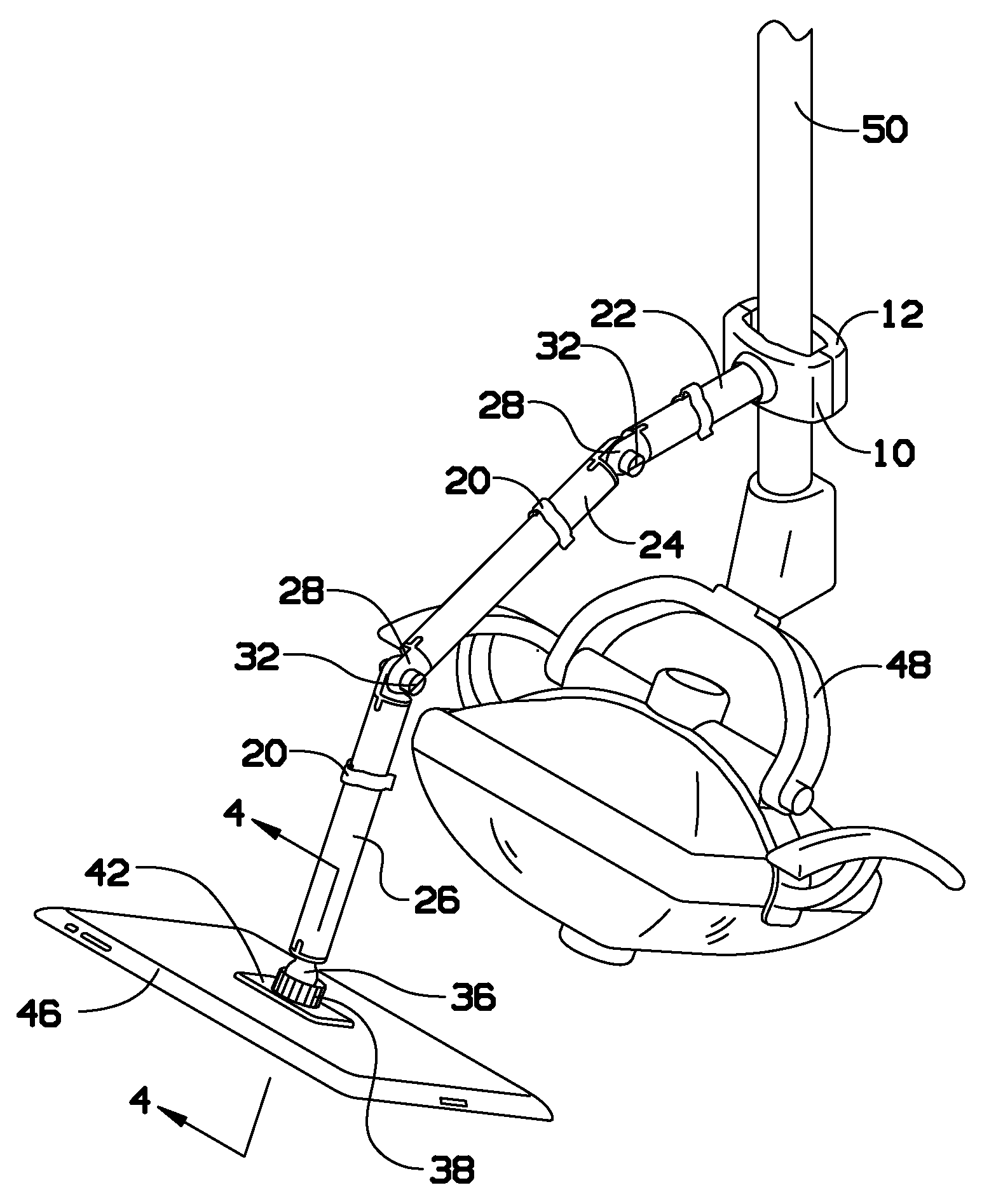
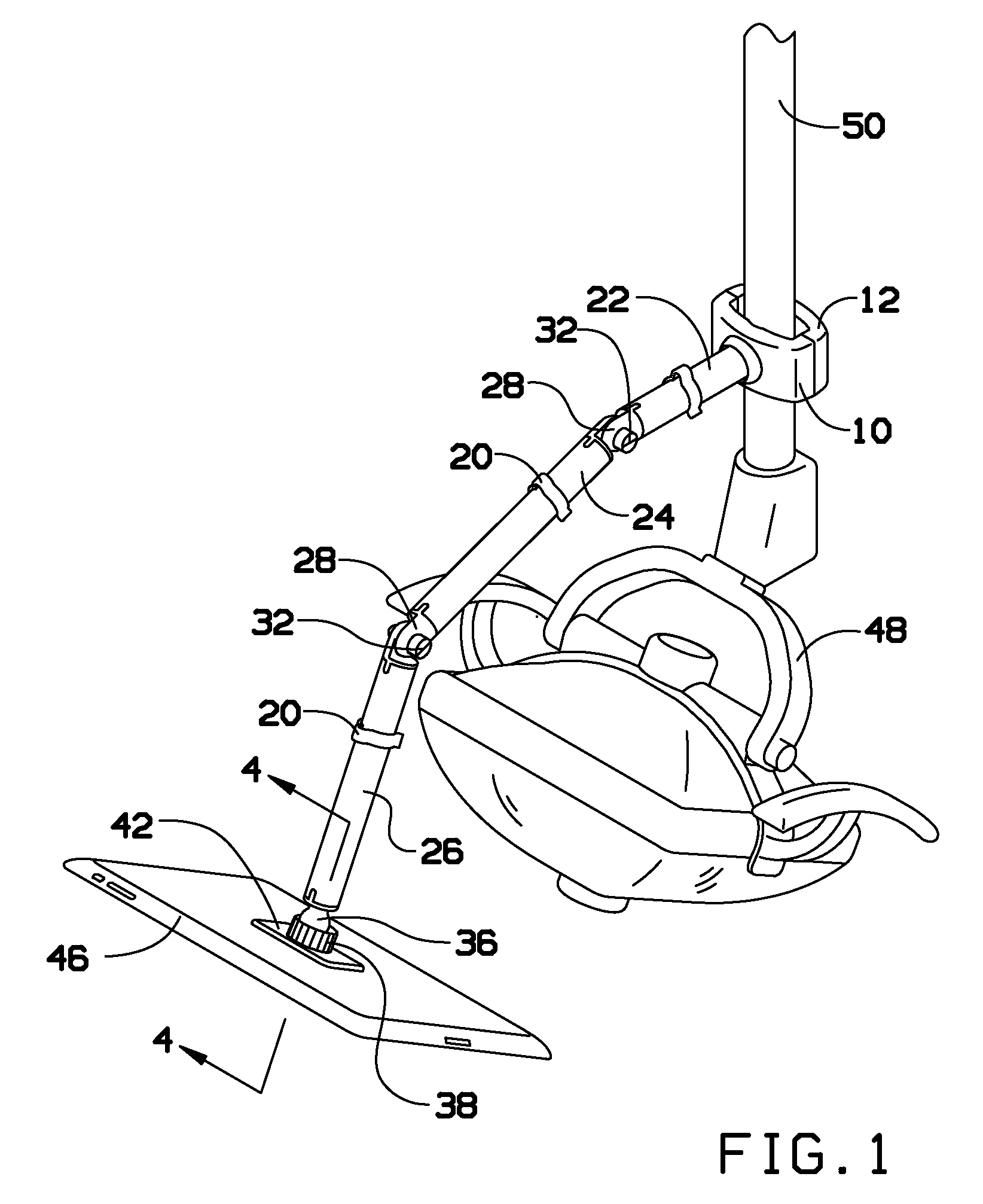
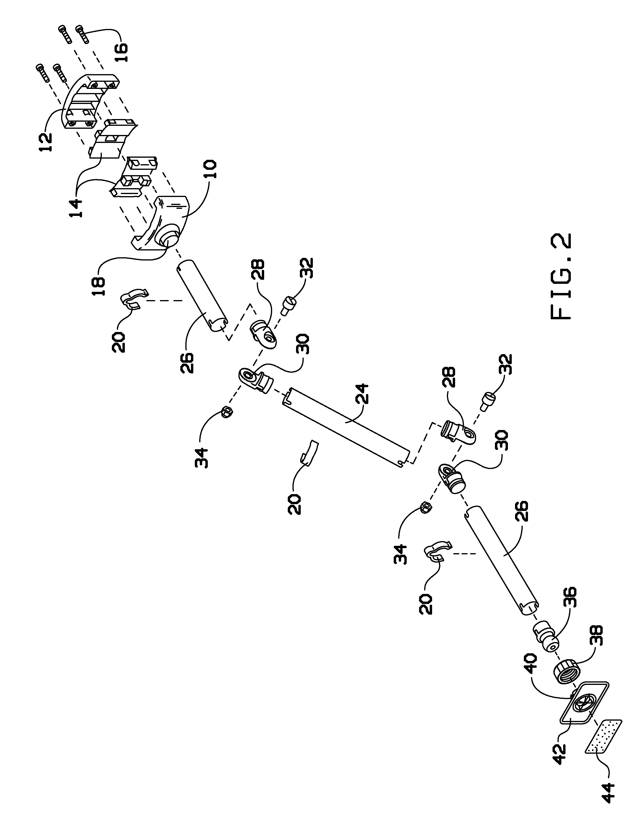
[0018]Some embodiments of the invention provide a molar media mount for positioning a media display device in a direct line of sight of a patient. In some embodiments, the molar media mount comprises a first end that attaches to a mounting arm of a medical device and a second end that attaches to and holds the media display device. In some embodiments, the second end comprises a ball joint for setting an angle of the media display device that corresponds to the direct line of sight. In some embodiments, the molar media mount comprises a set of articulating points that position a media display screen in a direct line of sight of a person in an examination seat In...


PUM


Abstract

Some embodiments provide a molar media mount for positioning a media display device in unobscured view and direct line of sight of a patient. In some embodiments, the molar media mount includes a first end that attaches to a mounting arm of a medical device and a second end that attaches to and holds the media display device. In some embodiments, the second end includes a ball joint for setting an angle of the media display device that corresponds to the direct line of sight. In some embodiments, the molar media mount includes a set of articulating points that position a media display screen in a direct line of sight of a person in an examination seat In some embodiments, the medical device is a dental light. In some embodiments, the media display device attaches to the dental light.

Description

CLAIM OF BENEFIT TO PRIOR APPLICATION[0001]This application claims benefit to U.S. Provisional Patent Application 61 / 682,013, entitled “An arm that attaches to dental light and holds a media device for patient viewing,” filed Aug. 10, 2012. The U.S. Provisional Patent Application 61 / 682,013 is incorporated herein by reference.BACKGROUND[0002]The embodiments herein relate generally to media device mounts, and more particularly to media device mounts for patient viewing in dental offices.[0003]Media devices are often provided in medical offices and exam rooms to display media content for patients to view during an examination or a procedure. For instance, a video display device may be available in a dental office to allow dental patients to watch an entertaining video during a dental procedure. A variety of content can be displayed on these display devices for a variety of needs. For example, display devices may be used to display images or video of a patient's tissue or body part(s) ...

Claims


Application Information

Patent Timeline
Patent Type & Authority Patents(United States)
IPC IPC(8): A47H1/10A61C1/08A61G15/14F16M11/14F16M11/20F16M13/02H05K5/00H05K5/02
CPCH05K5/0017H05K5/0217A61C1/088A61G15/14F16M11/14F16M11/2021F16M13/02F16M2200/022Y10S248/921
Inventor CULBERSON, CASEY F
Owner CULBERSON CASEY F
Why Eureka
Try Eureka