Unlock instant, AI-driven research and patent intelligence for your innovation.

Calibration method for tool center point of a robot manipulator

a robot manipulator and tool center point technology, applied in the direction of instrumentation, electric programme control, program control, etc., can solve the problems of manual calibration of the position of the tool center point, time-consuming and inconvenient, and the inability to guarantee the accuracy of manually calibrating the tool center poin

Active Publication Date: 2015-04-07
CLOUD NETWORK TECH SINGAPORE PTE LTD +1
View PDF5 Cites 3 Cited by
  • Summary
  • Abstract
  • Description
  • Claims
  • Application Information

AI Technical Summary

Benefits of technology

The patent text discusses the use of robot manipulators in industrial settings for various tasks. These robots have a tool attached to their end, like a cutting device or a gripper, that has a specific point called the Tool Center Point (TCP). The robot control system needs to know where this point is located in order to accurately perform its tasks. However, the tool may be mounted on the robot's end manually, which can lead to alignment errors and make it difficult to accurately position the TCP. This requires time-consuming and inconvenient manual calibration, and the precision of the calibration is not guaranteed. The technical effect of this patent is to provide a solution to this problem by automatically calibrating the position of the TCP, so that the robot can accurately perform its tasks without requiring manual adjustment.

Problems solved by technology

Since the tool may have been mounted to the distal end of the robot manipulator manually, an alignment error may arise between the tool and the robot manipulator, thereby causing the TCP to deviate from its expected position relative to the robot's distal end.
Manual calibration of the position of the tool center point is time-consuming and inconvenient, and the precision of manually calibrating the tool center point is not guaranteed.

Method used


Image

  • Calibration method for tool center point of a robot manipulator
  • Calibration method for tool center point of a robot manipulator
  • Calibration method for tool center point of a robot manipulator

Examples


Embodiment Construction

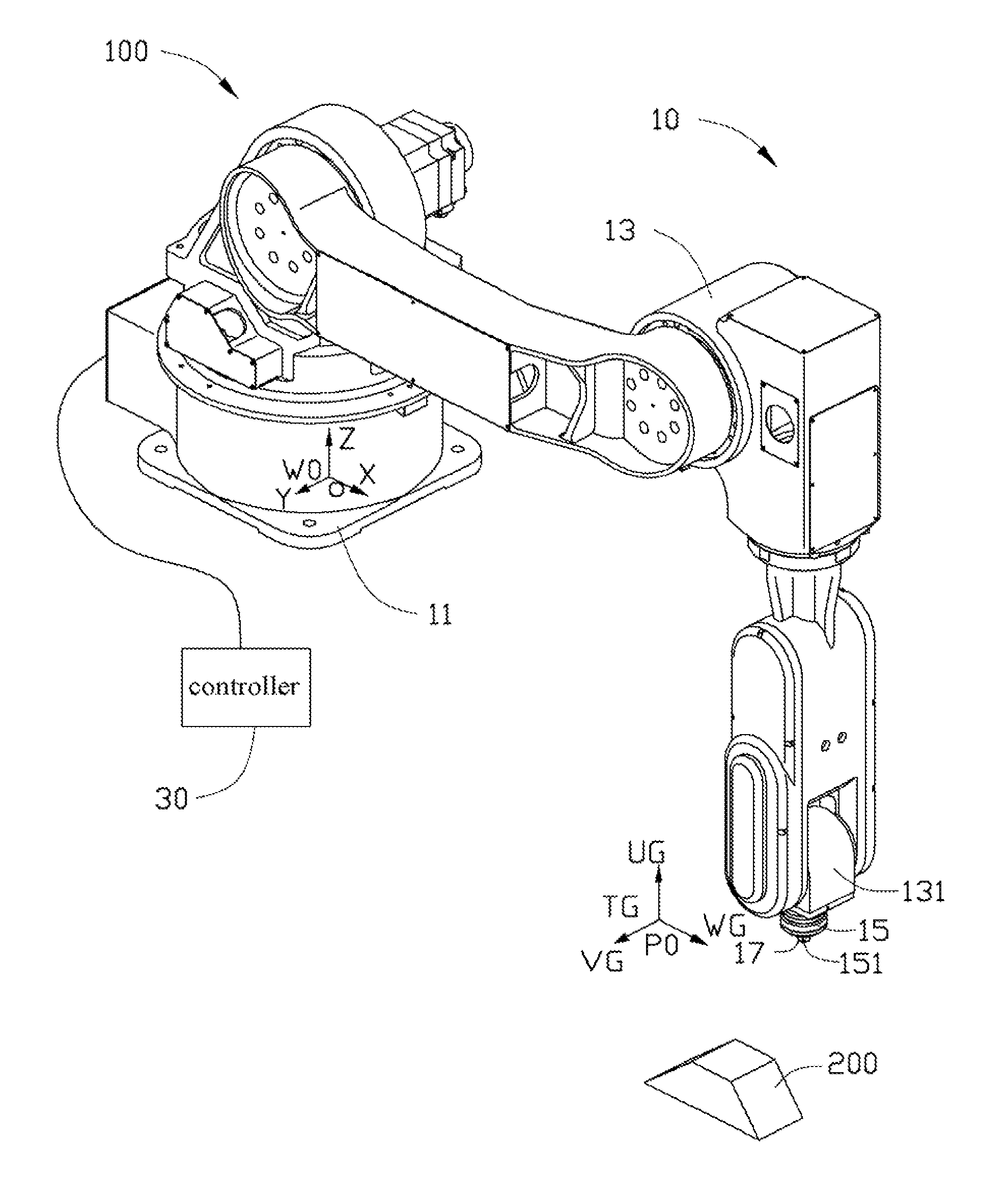
[0011]FIGS. 2 and 3, is an embodiment of a robot manipulator 100 together with a assistant indicating tool 200. The robot manipulator 100 includes a main body 10 and a controller 30 connected to the main body 10. The main body 10 includes a plurality of multiple mechanical linkages including a base 11, a drive mechanism 13, a tool 15 and a sensor 17. The drive mechanism 13 includes all physical components (such as motors, gears, and mechanical linkages) required to move the tool 15. The drive mechanism 13 is mounted on the base 11 and connected with the controller 30. The drive mechanism 13 includes an end mechanical linkage 131 at an end of the drive mechanism 13 away from the base 11. The tool 15 is assembled to a distal end of the end mechanical linkage 131. The sensor 17 is mounted on a distal end of the tool 15 for detecting or measuring a distance between the sensor 17 and the assistant indicating tool 200.

[0012]The controller 30 includes a preset control software (not shown a...


PUM

PropertyMeasurementUnit
included angleaaaaaaaaaa
rotating angleaaaaaaaaaa
rotation angleaaaaaaaaaa

Abstract

A calibration method for calibration a tool center point for a robot manipulator includes the steps of: driving the tool to move above one of the inclined surfaces; defining a preset coordinate system TG; rotating the TCP relative to the UG-axis by about 180 degrees, calculating the value of Δw; updating the position parameters of the preset TCP, defining a new preset coordinate system TG′; rotating the TCP relative to the UG′-axis by about 90 degrees, calculating the value of Δv; updating the position parameters of the new preset TCP, defining a new preset coordinate system TG″; driving the tool to move above a planar horizontal surface; rotating the TCP relative to a axis by about 30 degrees, calculating the value of Δu; repeating the aforementioned steps until the deviation ΔP (Δw, Δv, Δu) is less than or equal to a maximum allowable deviation of the robot manipulator.

Description

BACKGROUND[0001]1. Technical Field[0002]The present disclosure generally relates to calibration methods for robot manipulators, and particularly to a calibration method for a tool center point of a robot manipulator.[0003]2. Description of Related Art[0004]Robot manipulators are used in various industrial fields to fulfill the task requirements for product assembling, welding and other tasks automatically. A robot manipulator of related art may be equipped with a tool, such as a cutting device, a gripper, a glue dispenser or a fixture mounted to a distal end. The tool has a specific defined point, called the Tool Center Point (TCP), that is commanded to move to various positions in the workspace when a robot manipulator performs a task. In use, the operating accuracy of the robot manipulator directly depends on a robot control system knowing the precise position of the TCP relative to the robot manipulator's distal end. Since the tool may have been mounted to the distal end of the r...

Claims


Application Information

Patent Timeline
Patent Type & Authority Patents(United States)
IPC IPC(8): G05B19/04G01L25/00B25J9/16
CPCB25J9/1692
Inventor CHIU, LONG-ENWU, YONG
Owner CLOUD NETWORK TECH SINGAPORE PTE LTD