Logic diagram processing device and logic diagram processing method

a logic diagram and processing device technology, applied in the direction of electric controllers, instruments, ignition automatic control, etc., can solve the problems of increasing the number of devices to be controlled, increasing the complexity of control logics, and increasing the difficulty of maintenance work such as analysis, addition and editing of existing programs, so as to achieve efficient comparison and collation of a plurality of logic diagrams

Active Publication Date: 2015-05-12
MITSUBISHI ELECTRIC CORP
View PDF11 Cites 0 Cited by
  • Summary
  • Abstract
  • Description
  • Claims
  • Application Information

AI Technical Summary

Benefits of technology

[0015]The present invention has been achieved in consideration of the drawbacks as described above, and an object of the present invention is to provide a technique capable of efficiently comparing and collating a plurality of logic diagrams.
[0017]By displaying a plurality of logic diagrams in which operation elements are relocated while maintaining control logics equivalently and which are overlapped in a predetermined display method by which a common part or the difference of the operation elements can be discriminated and switching the predetermined display method in accordance with an instruction from the outside, a plurality of diagrams can be efficiently compared and collated. Therefore, time for comparison and collation can be reduced and a human error in a comparing operation can be prevented, so that the quality of monitor and control process can be also improved.

Problems solved by technology

In recent years, as the scale of a program is becoming large-scaled, maintenance work such as analysis, addition, and editing of an existing program is becoming difficult.
Concretely, since behaviors corresponding to various modes are written in control logic diagrams, control logics tend to be complicated.
In addition, since the number of devices to be controlled is large, the number of logic diagrams controlling the devices is also enormous.
However, in a pictorial representation language such as a logic diagram, in the case where a diagram is generated without copying or the case where, even diagrams are copied, the copy sources are different, layouts are usually different, and it is difficult to find the difference at a glance.
. . , it is more difficult to compare and collate them.
The conventional method, therefore, requires long work time for comparison of logic diagrams.
There is the possibility of occurrence of a check error and oversight, and the method has a problem that the quality of a control logic generated is low.
As described above, in a pictorial representation language such as a logic diagram, there is a challenge to efficiently collate the difference between similar diagrams.
As a result, in the case where the number of logic diagrams to be compared is large, a problem occurs such that the diagrams cannot be efficiently compared and collated.

Method used


Image

  • Logic diagram processing device and logic diagram processing method
  • Logic diagram processing device and logic diagram processing method
  • Logic diagram processing device and logic diagram processing method

Examples


first embodiment

[0038

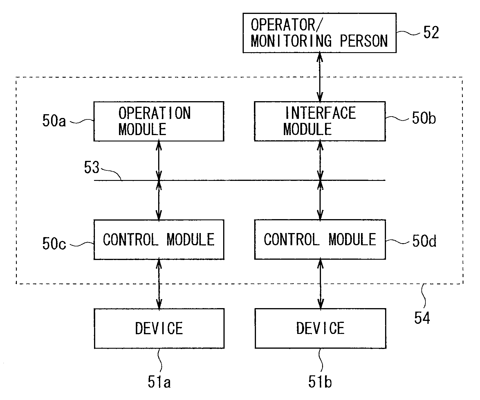
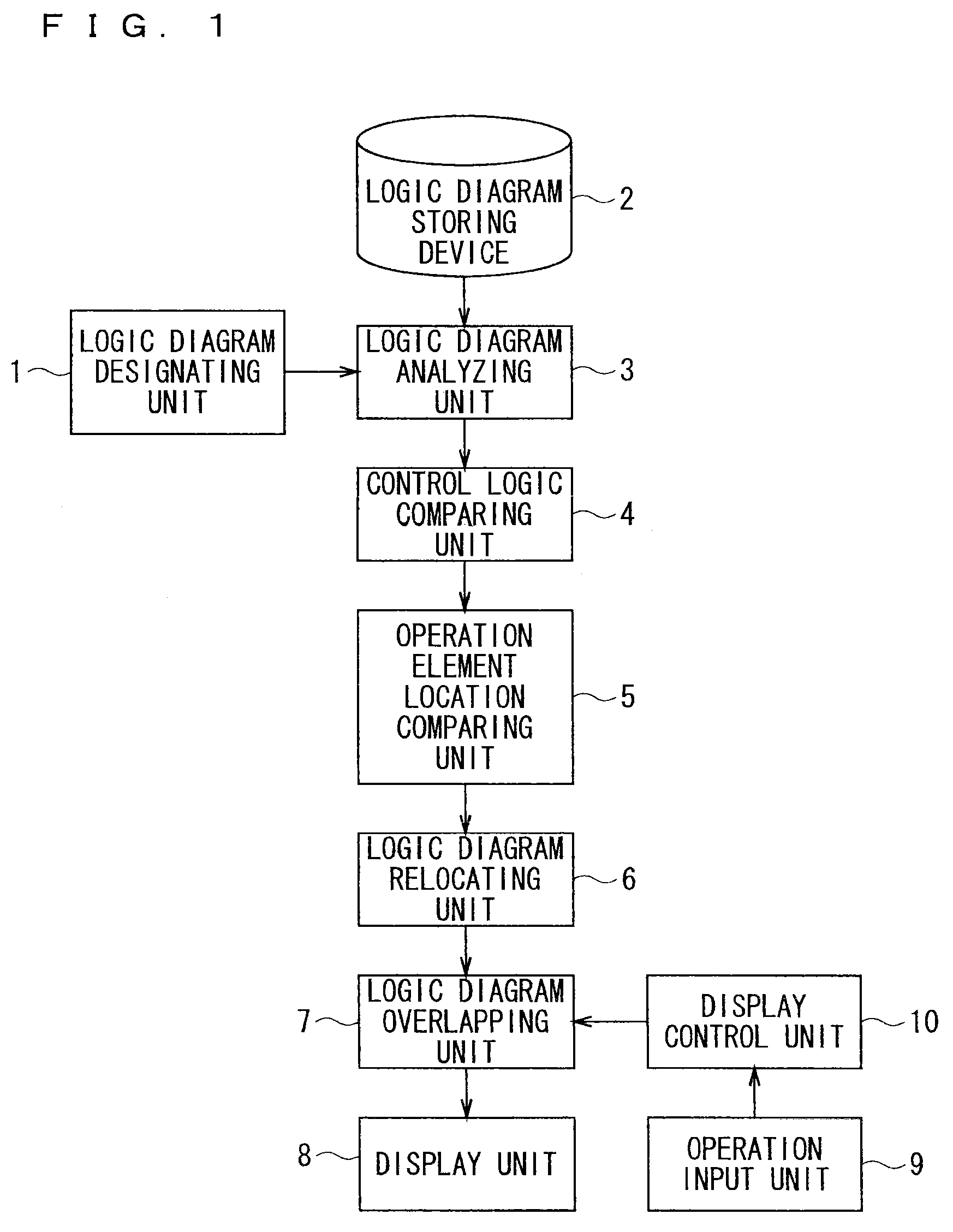
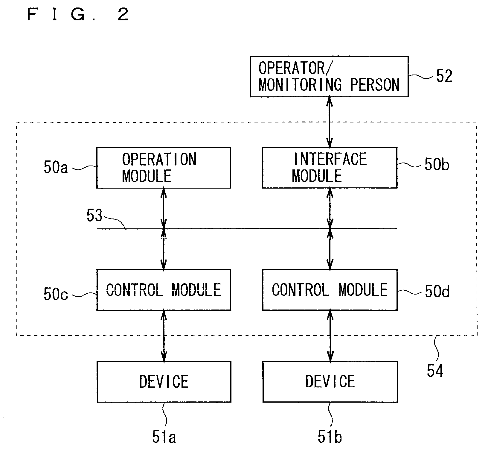
[0039]FIG. 1 is a block diagram illustrating the configuration of a logic diagram display device (logic diagram processing device) according to a first embodiment. In the first embodiment, the contents (control logics) of monitor and control performed on devices by a monitor control system are illustrated in logic diagrams, and the logic diagram display device of the preferred embodiment is a device for displaying a plurality of logic diagrams. The logic diagram will be described in detail later.

[0040]As illustrated in FIG. 1, the logic diagram display device of the preferred embodiment has a logic diagram designating unit 1, a logic diagram storing device 2 storing logic diagrams of a plurality of devices, a logic diagram analyzing unit 3, a control logic comparing unit 4, an operation element location comparing unit 5, a logic diagram relocating unit 6, a logic diagram overlapping unit 7, a display unit 8, an operation input unit 9, and a display control unit 10.

[0041]The log...

second embodiment

[0084

[0085]FIG. 10 is a block diagram illustrating the configuration of a logic diagram editing device (logic diagram processing device) according to a second embodiment of the present invention. In the logic diagram editing device according to the preferred embodiment, the same reference numerals are designated to components which are the same as or similar to those described in the first embodiment, and points different from the first embodiment will be mainly described.

[0086]In the first embodiment, the logic diagrams are displayed in the display unit 8. The logic diagram editing device according to the second embodiment can edit a logic diagram displayed in the display unit 8 in accordance with an instruction from the outside.

[0087]In the first embodiment, a logic diagram viewer himself / herself designates a plurality of logic diagrams to be displayed in the logic diagram designating unit 1 and they are overlapped and displayed. However, the number of logic diagrams is enormous i...


PUM


Abstract

A logic diagram processing device has a logic diagram relocating unit which relocates operation elements while maintaining control logics equivalently so that the operation elements as compared overlap in the case where a plurality of designated logic diagrams are overlapped, and a logic diagram overlapping unit which overlaps the plurality of designated logic diagrams in which the operation elements are relocated by the logic diagram relocating unit. The logic diagram processing device also includes a display unit which displays the plurality of designated logic diagrams overlapped by the logic diagram overlapping unit in a predetermined display method by which a common part or the difference of the operation elements can be discriminated, and a display control unit which switches the predetermined display method to display in the display unit in accordance with an instruction from the outside.

Description

BACKGROUND OF THE INVENTION[0001]1. Field of the Invention[0002]The present invention relates to a logic diagram processing device and a logic diagram processing method for processing a logic diagram expressing content of monitor and control performed on a device by a monitor and control system.[0003]2. Description of the Background Art[0004]A monitor and control system notifies an operator / observer of information from a device to be monitored such as various sensors of temperature, pressure, position, and the like and controls various devices such as a motor, a valve, a switch, and hydraulic equipment by an operation of the operator / observer, and is used in a wide range of fields such as a power generation plant, a chemical plant, power receiving / distributing equipment, and water supply and sewerage systems.[0005]A typical monitor and control system has a plurality of modules divided by processes, for example, performing transmission / reception of signals to / from a device as an obje...

Claims


Application Information

Patent Timeline
Patent Type & Authority Patents(United States)
IPC IPC(8): G05B15/02G05B23/02
CPCG05B15/02G05B23/0216Y02T10/82
Inventor YOSHINAGA, MITSUNOBUOI, TADASHITSUDAKA, SHINICHIRONAKAGAWA, MASAYO
Owner MITSUBISHI ELECTRIC CORP
Why Eureka
Try Eureka