Fuel cell stack used as coolant heater

a fuel cell and stack technology, applied in the field of system and method for heating a fuel cell stack, can solve the problem of inefficient stack operation, and achieve the effect of increasing the temperature of the fuel cell stack quickly

Active Publication Date: 2015-05-19
GM GLOBAL TECH OPERATIONS LLC
View PDF8 Cites 2 Cited by
  • Summary
  • Abstract
  • Description
  • Claims
  • Application Information

AI Technical Summary

Benefits of technology

[0010]In accordance with the teachings of the present invention, a system and method are disclosed for increasing the temperature of a fuel cell stack quickly, especially at cold stack start-up. The method includes determining whether the fuel cell stack is below a first predetermined temperature threshold, and, if so, starting a cooling fluid flow through the stack at normal or lower flow rates and engaging a shorting circuit across the stack, or any type of electrical load, to clamp the stack voltage close to 0V during the hydrogen fill of the anode so as to short circuit the stack and cause the stack to operate inefficiently. The method then determines a desired heating rate of the fuel cell stack and calculates a cathode airflow to the fuel cell stack based on the desired heating rate. The method reduces the flow of cathode air to the stack if a minimum cell voltage is below a predetermined minimum cell voltage threshold and disengages the shorting circuit and applies vehicle loads to the stack when the stack temperature reaches a second predetermined temperature threshold.

Problems solved by technology

The method includes determining whether the fuel cell stack is below a first predetermined temperature threshold, and, if so, starting a cooling fluid flow through the stack at normal or lower flow rates and engaging a shorting circuit across the stack, or any type of electrical load, to clamp the stack voltage close to 0V during the hydrogen fill of the anode so as to short circuit the stack and cause the stack to operate inefficiently.

Method used


Image

  • Fuel cell stack used as coolant heater
  • Fuel cell stack used as coolant heater
  • Fuel cell stack used as coolant heater

Examples


Embodiment Construction

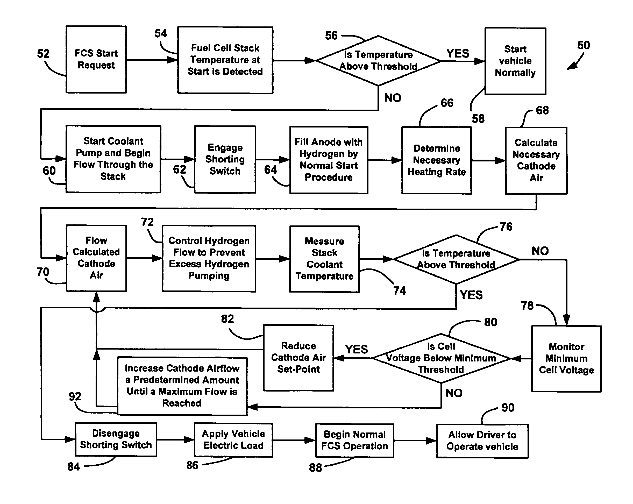
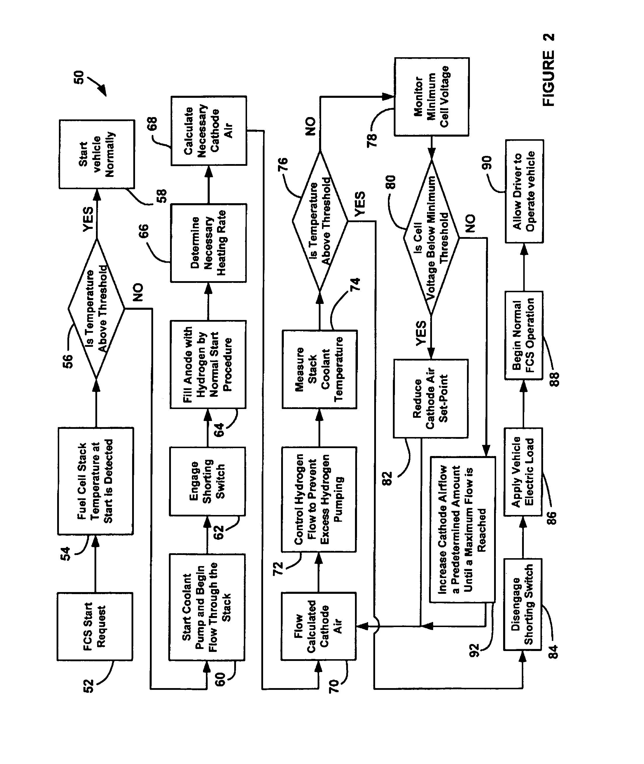
[0014]The following discussion of the embodiments of the invention directed to a system and method for heating a fuel cell stack at cold stack start-up by shorting the terminals of the stack is merely exemplarary in nature, and is in no way intended to limit the invention or its applications or uses.

[0015]The present invention proposes a system and method for reducing the time required for a fuel cell stack to warm-up in cold temperatures to a desired minimum operating temperature. Cold system starts can be any start in which the temperature of the cooling fluid that cools the stack or the stack internal temperature on the bipolar plates or end plates is lower than the normal stack operating temperature. A predetermined cold-start temperature Tcold-start can be defined through experimentation. If the stack is above the cold-start temperature Tcold-start, the fuel cell system will start with normal algorithms. However, if the cooling fluid temperature is below the cold-start temperat...


PUM

PropertyMeasurementUnit
temperatureaaaaaaaaaa
voltageaaaaaaaaaa
stack voltageaaaaaaaaaa

Abstract

A system and method for increasing the temperature of a fuel cell stack quickly, especially at cold stack start-up. The method includes determining whether the fuel cell stack is below a first predetermined temperature threshold, and, if so, starting a cooling fluid flow through the stack and engaging a shorting circuit across the stack to short circuit the stack and cause the stack to operate inefficiently. The method then determines a desired heating rate of the fuel cell stack and calculates a cathode airflow to the fuel cell stack based on the desired heating rate. The method reduces the flow of cathode air to the stack if a minimum cell voltage is below a predetermined minimum cell voltage threshold and disengages the shorting circuit and applies vehicle loads to the stack when the stack temperature reaches a predetermined second temperature threshold.

Description

BACKGROUND OF THE INVENTION[0001]1. Field of the Invention[0002]This invention relates generally to a system and method for heating a fuel cell stack at system start-up and, more particularly, to a system and method for heating a fuel cell stack system start-up that includes electrically shorting the stack and using cathode air as a limiting reactant.[0003]2. Discussion of the Related Art[0004]Hydrogen is a very attractive fuel because it is clean and can be used to efficiently produce electricity in a fuel cell. A hydrogen fuel cell is an electro-chemical device that includes an anode and a cathode with an electrolyte therebetween. The anode receives hydrogen gas and the cathode receives oxygen or air. The hydrogen gas is dissociated in the anode to generate free hydrogen protons and electrons. The hydrogen protons pass through the electrolyte to the cathode. The hydrogen protons react with the oxygen and the electrons in the cathode to generate water. The electrons from the anode ...

Claims


Application Information

Patent Timeline
Patent Type & Authority Patents(United States)
IPC IPC(8): H01M8/04
CPCH01M8/04089H01M8/04268H01M8/04365H01M8/04552H01M8/04731Y02E60/50
Inventor LEBZELTER, DEREK RLAKSHMANAN, BALASUBRAMANIANWAGNER, FREDERICK T.
Owner GM GLOBAL TECH OPERATIONS LLC
Why Eureka
Try Eureka