Floor box cover assembly

a technology for floor boxes and assembly, applied in the direction of electrical appliances, etc., can solve the problems of interference with the use of the box

Active Publication Date: 2015-05-19
HUBBELL INC
View PDF50 Cites 11 Cited by
  • Summary
  • Abstract
  • Description
  • Claims
  • Application Information

AI Technical Summary

Benefits of technology

[0018]The present invention is directed to a floor box cover assembly where the cover pivots 180° between a closed position and an open position. The invention is particularly directed to cover assembly where the cover can pivot to an open position and lay flat on the floor surface without interference from the base of the cover assembly on the floor surface.
[0019]Accordingly one object of the invention is to provide a cover assembly for a floor box having a hinge assembly that enables the pivoting of the cover between a closed position where the cover is flush with the top surface of the base and an open position where the cover can lay flat on the floor.
[0020]Another feature of the invention is to provide a cover assembly having a hinge assembly with a hinge body that is pivotally connected to the base and pivotally connected to the cover. The hinge assembly enables a free range of movement of the cover with respect to the base.
[0021]A further feature of the invention is to provide a cover assembly for a floor box having a base and hinged cover. The base has a surface that contacts an edge of the cover during opening and closing of the cover to form a sliding surface to prevent excess wear to a gasket provided between the cover and the base. The gasket is positioned within a central opening of the base to form a seal between the cover and the base. The sliding surface is provided to contact the pivoting end of the cover during opening and closing to prevent sliding contact of the cover with the gasket and to guide the end of the cover to the closed position.
[0023]The cover assembly of the invention includes a hinge assembly that enables the cover to pivot to lay flat on the floor in the open position. The hinge assembly has a hinge body with one end pivotally coupled to a first end of the base and a second end pivotally coupled to a first end of the cover. The second end of the hinge body has a tab that extends from the hinge body to contact the bottom surface of the cover to limit pivoting movement of the cover with respect to the hinge body. The tab enables the hinge body to pivot with the cover about the pivot axis between the base and the hinge body while closing the cover.

Problems solved by technology

Many floor boxes have a top surface that is raised from the floor creating a lip that interferes with the use of the box.

Method used


Image

  • Floor box cover assembly
  • Floor box cover assembly
  • Floor box cover assembly

Examples


Embodiment Construction

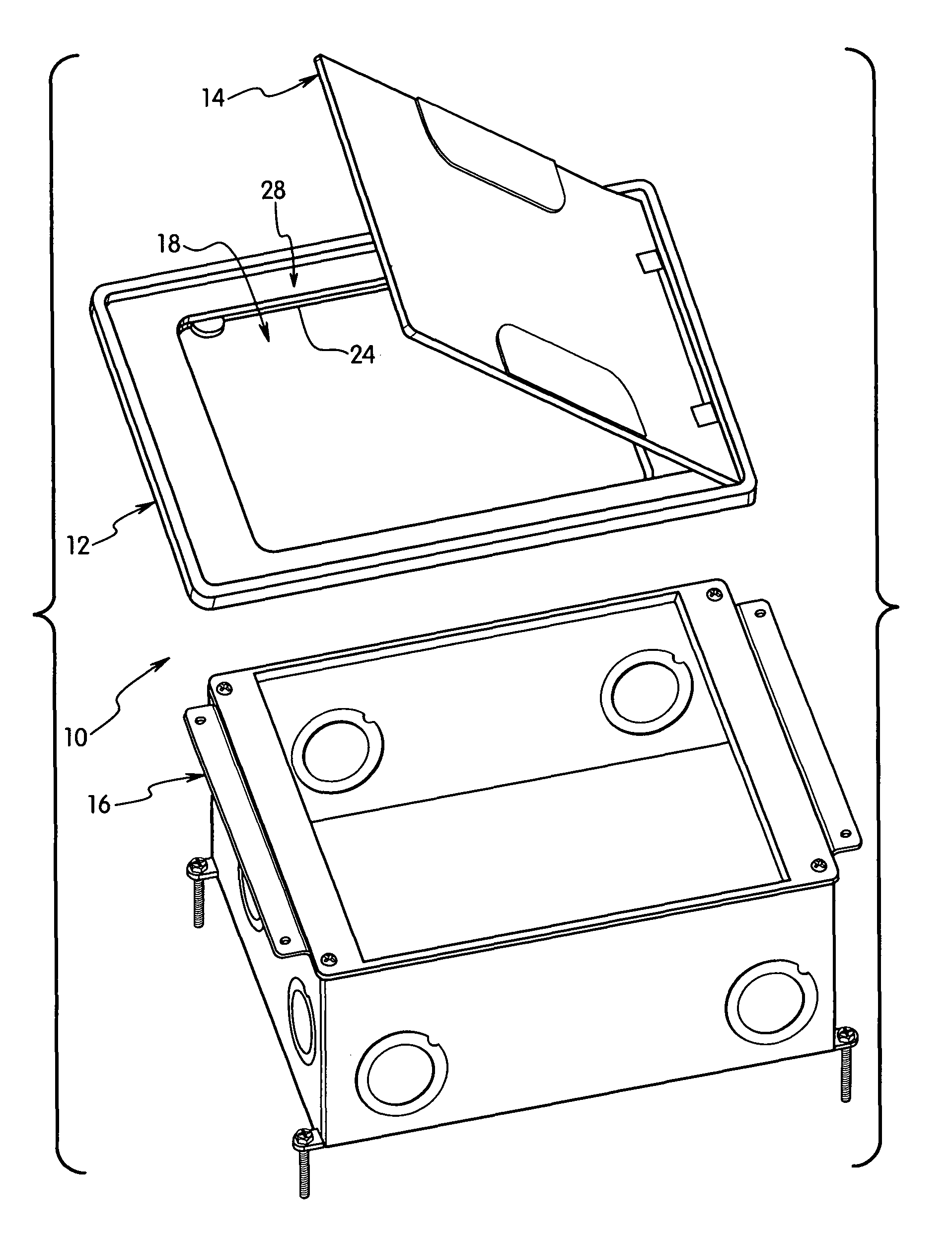
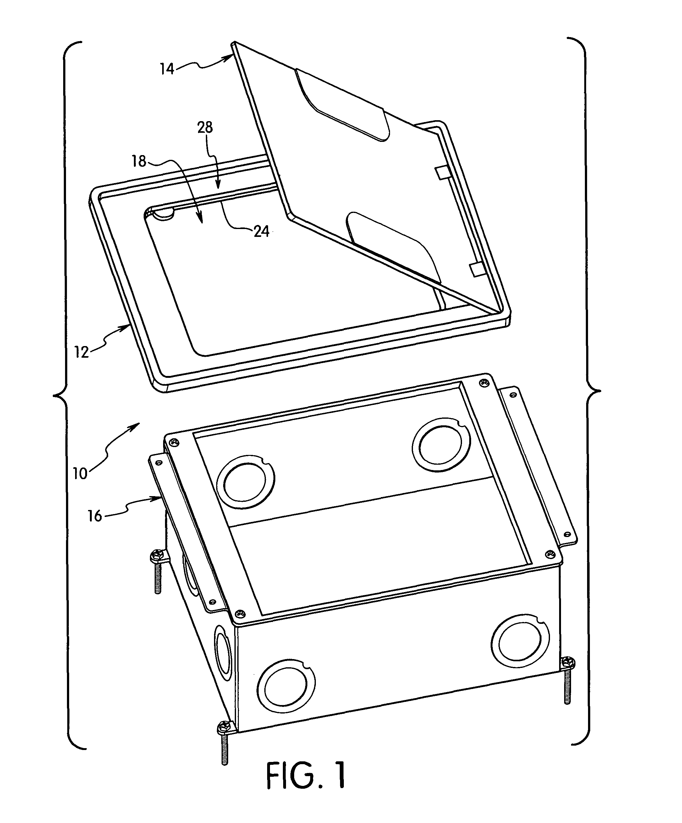
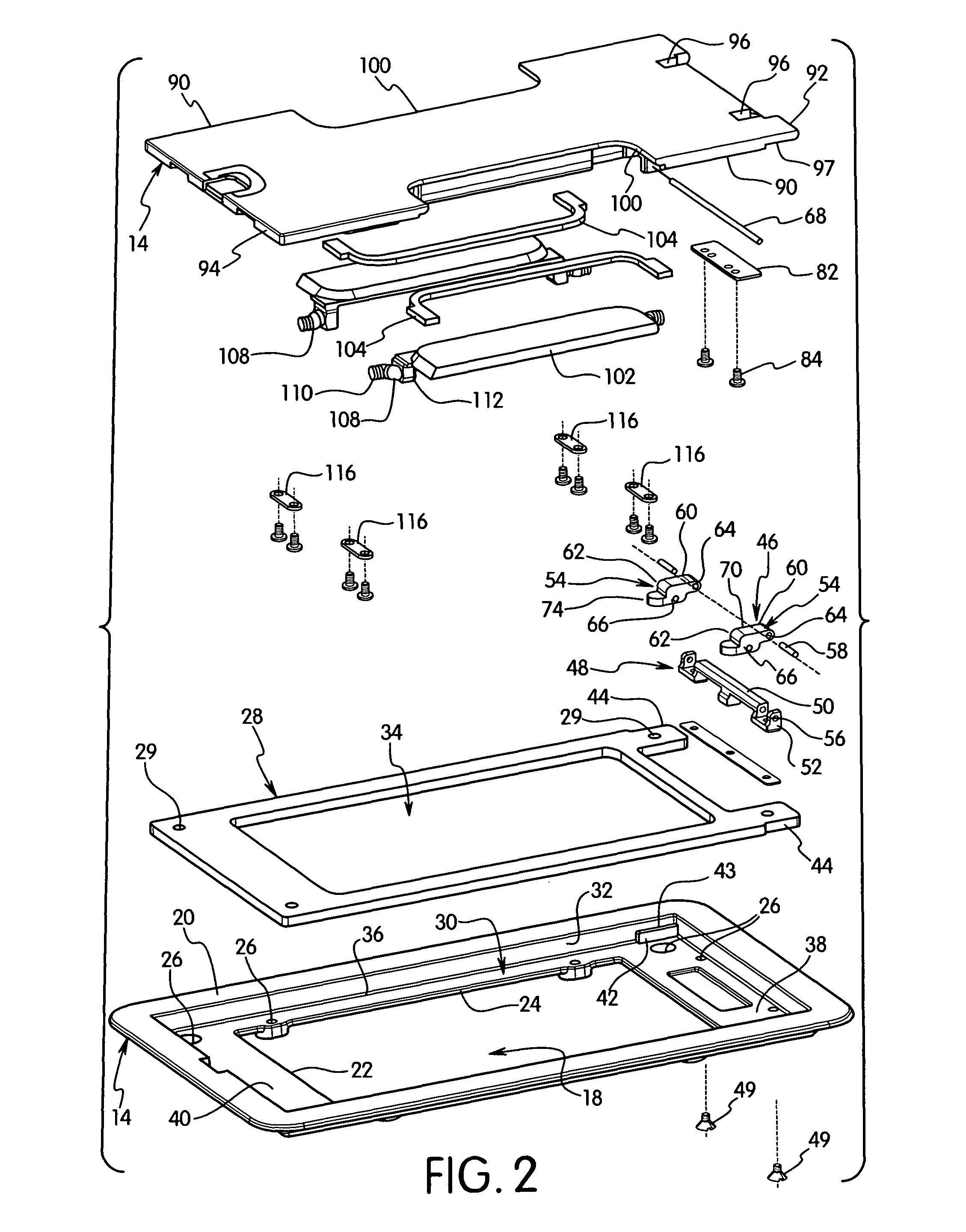
[0059]The present invention is directed to a cover assembly for an electrical box. In particular, the invention is directed to a cover assembly for use with a floor box that is mounted in a floor to allow access to electrical components mounted in the box.

[0060]The cover assembly of the invention as shown in the drawings includes a cover assembly 10 having a base 12 and cover 14. The cover assembly 10 is configured to coupling to an electrical box 16. The electrical box 16 in the embodiment shown is a floor mounted box that is intended to be mounted in the floor of a building so that the electrical components are accessible to the user. The electrical box 16 can be any suitable construction as known in the art and is mounted in the floor so that the top edge is substantially flush with the floor surface. In the embodiment shown, the electrical box 16 has an open top end configured for coupling to the cover assembly. The electrical box 16 typically encloses electrical wiring device s...


PUM


Abstract

A cover assembly for a floor box includes a base with a central opening and a cover pivotally connected to the base by a hinge member. The hinge member has a hinge body with a first end pivotally connected to the base for pivoting with respect to the base and second end pivotally connected to the cover for pivoting with respect to the cover. A tab extends from the second end of the hinge body to contact a bottom surface of the cover to limit pivoting movement of the cover with respect to the hinge body. A slide surface is provided on the base that contacts an end of the cover during pivoting movement of the cover to prevent wear on a gasket with the opening of the base.

Description

FIELD OF THE INVENTION[0001]The present invention is directed to a cover assembly having a base and a hinged cover that pivots about 180° between an open position and closed position. The invention is particularly directed to a cover assembly having a hinge assembly that permits the cover to lay flat on the floor in the open position.BACKGROUND OF THE INVENTION[0002]Electrical floor boxes are known in the art for covering electrical receptacle and other electrical devices when not in use. Often the floor box has a hinged cover that pivots from a closed position to an open position. Many floor boxes have a top surface that is raised from the floor creating a lip that interferes with the use of the box.[0003]One example of prior a floor box is disclosed in U.S. Patent Publication No. 2010 / 0072198 to Roemer et al. This patent application discloses a floor mounting container for an electrical device where the cover can pivot 180° to lay flat in the open position. The hinge includes a hi...

Claims


Application Information

Patent Timeline
Patent Type & Authority Patents(United States)
IPC IPC(8): H02G3/14H02G3/08
CPCH02G3/081H02G3/14H02G3/088H02G3/12H02G3/185
Inventor SCANZILLO, THOMAS L.MARCHETTI, MICHAEL J.CARBONE, CHRISTOPHER A.PAPAGEORGE, RYAN G.
Owner HUBBELL INC
Why Eureka
Try Eureka