
Transmission method and apparatus for carrier aggregation and uplink MIMO

a transmission method and carrier aggregation technology, applied in multiplex communication, wireless commuication services, site diversity, etc., can solve the problems of ineffective provision of ue rf architecture and difficulty for receivers to determine transmitted signals, and achieve efficient connection structures and maximize bandwidth expansion

Inactive Publication Date: 2015-05-19
LG ELECTRONICS INC
View PDF24 Cites 1 Cited by
  • Summary
  • Abstract
  • Description
  • Claims
  • Application Information

AI Technical Summary

Benefits of technology

This approach enables efficient connection structures between carrier aggregation and uplink MIMO, maximizing bandwidth expansion in wireless communication systems and enhancing data transfer reliability.

Problems solved by technology

In general, when a transport channel experiences deep fading, if a different version or a replica of a transmitted signal is not additionally transmitted, it is difficult for a receiver to determine the transmitted signal.
However, such UE RF architecture has not been effectively provided yet.

Method used


Image

  • Transmission method and apparatus for carrier aggregation and uplink MIMO
  • Transmission method and apparatus for carrier aggregation and uplink MIMO
  • Transmission method and apparatus for carrier aggregation and uplink MIMO

Examples


Embodiment Construction

[0029]Reference will now be made in detail to the preferred embodiments of the present invention, examples of which are illustrated in the accompanying drawings. It will also be apparent to those skilled in the art that various modifications and variations can be made in the present disclosure without departing from the spirit or scope of the invention. Thus, it is intended that the present disclosure cover modifications and variations of this invention provided they come within the scope of the appended claims and their equivalents.

[0030]It will be understood that, although the terms first, second, etc. may be used herein to describe various elements, these elements should not be limited by these terms. These terms are only used to distinguish one element from another. For example, a first element could be termed a second element, and, similarly, a second element could be termed a first element, without departing from the scope of the present disclosure. Term ‘and / or’ may represent...


PUM


Abstract

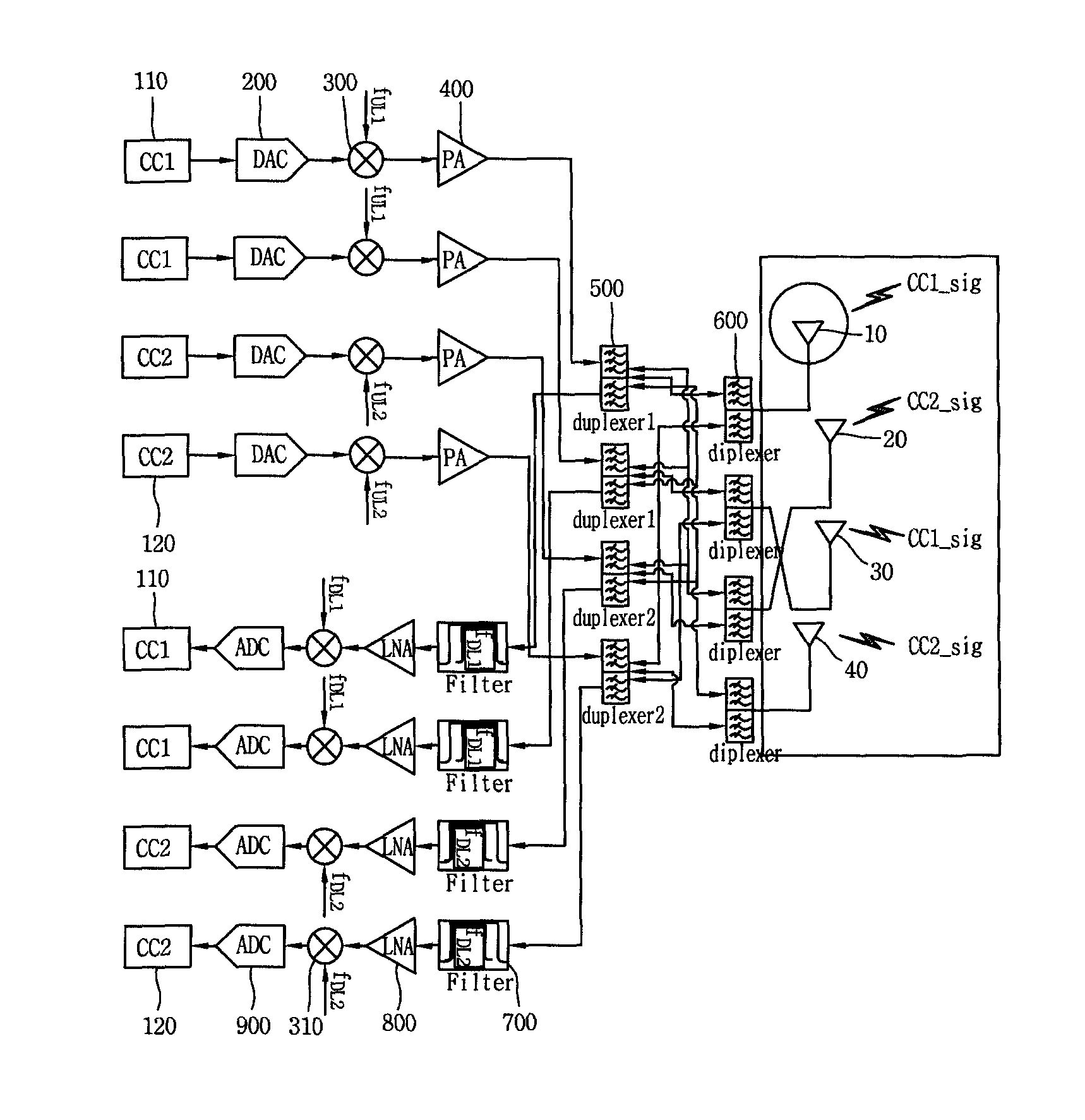
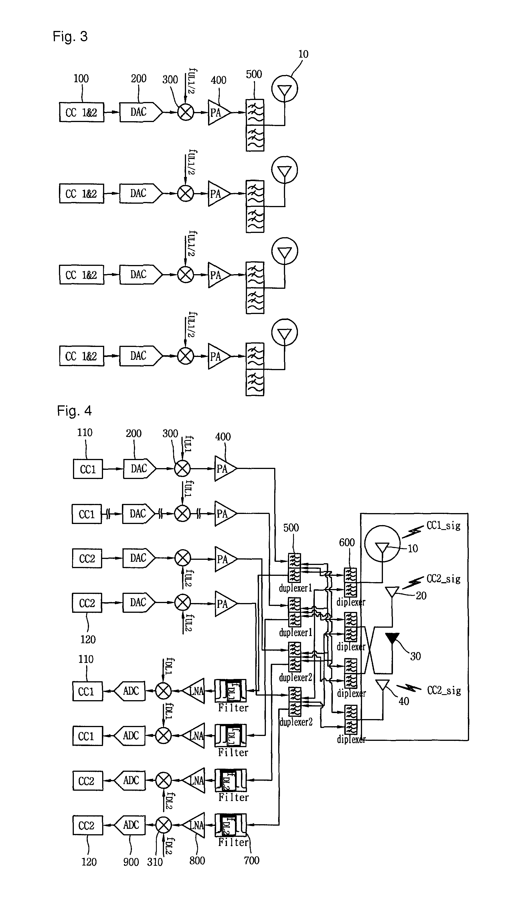
A transmission method for carrier aggregation, more particularly, for uplink MIMO and carrier aggregation, in a method for transmitting an uplink signal by the carrier aggregation in a terminal having at least four antennas, includes receiving a grant signal for transmission of the uplink signal, the grant signal including information related to use of a primary cell and a secondary cell, determining one antenna or at least two antennas to use the primary cell, determining one antenna or at least two antennas to use the secondary cell, and transmitting a first uplink signal to the primary cell and a second uplink signal to the secondary cell using the respective determined antennas.

Description

[0001]This application is the National Phase of PCT / KR2011 / 004933 filed on Jul. 6, 2011, which claims priority under 35 U.S.C. 119(e) to the U.S. Provisional Application No. 61 / 364,806 filed on Jul. 16, 2010, all which are hereby expressly incorporated by reference into the present application.TECHNICAL FIELD[0002]The present disclosure relates to transmission for carrier aggregation, and more particularly, a transmission method and apparatus for multi-antenna based carrier aggregation.BACKGROUND ART[0003]MIMO is a short term of Multi Input and Multi Output, and indicates an method for improving data transmission and reception efficiency by adapting a multiple transmit antenna and a multiple receive antenna, breaking with an method using one transmit antenna and one receive antenna. That is, the MIMO technology is to implement capacity increase and performance improvement by using multiple antennas at a transmitting end (transmitter) or a receiving end (receiver) in a wireless commu...

Claims


Application Information

Patent Timeline
Patent Type & Authority Patents(United States)
IPC IPC(8): H04W4/00H04B7/02H04B7/04H04B7/06
CPCH04B7/0413H04B7/022H04B7/0404H04B7/0613
Inventor LIM, SUHWANJUNG, MANYOUNGYANG, YOONOHLEE, SANGWOOK
Owner LG ELECTRONICS INC
Learn More