
Module for determining of reference values for a vehicle control system

a vehicle control and reference value technology, applied in the direction of braking systems, process and machine control, instruments, etc., can solve the problems of disturbing other traffic, difficult control system to determine how, and high fuel consumption of the vehicle, so as to reduce the amount of fuel needed and quickly calculate the set-point value

Inactive Publication Date: 2015-05-26
SCANIA CV AB
View PDF11 Cites 0 Cited by
  • Summary
  • Abstract
  • Description
  • Claims
  • Application Information

AI Technical Summary

Benefits of technology

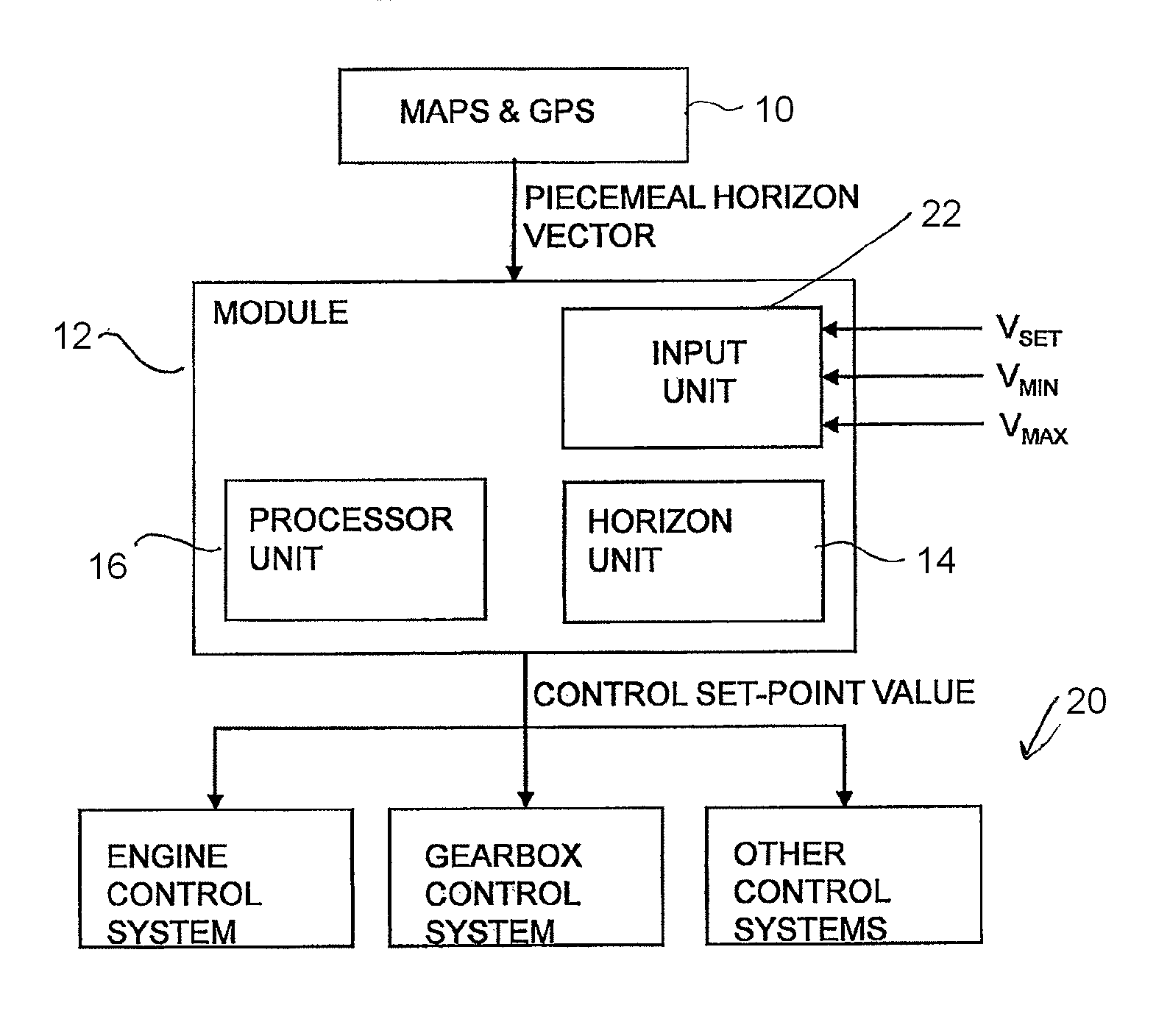
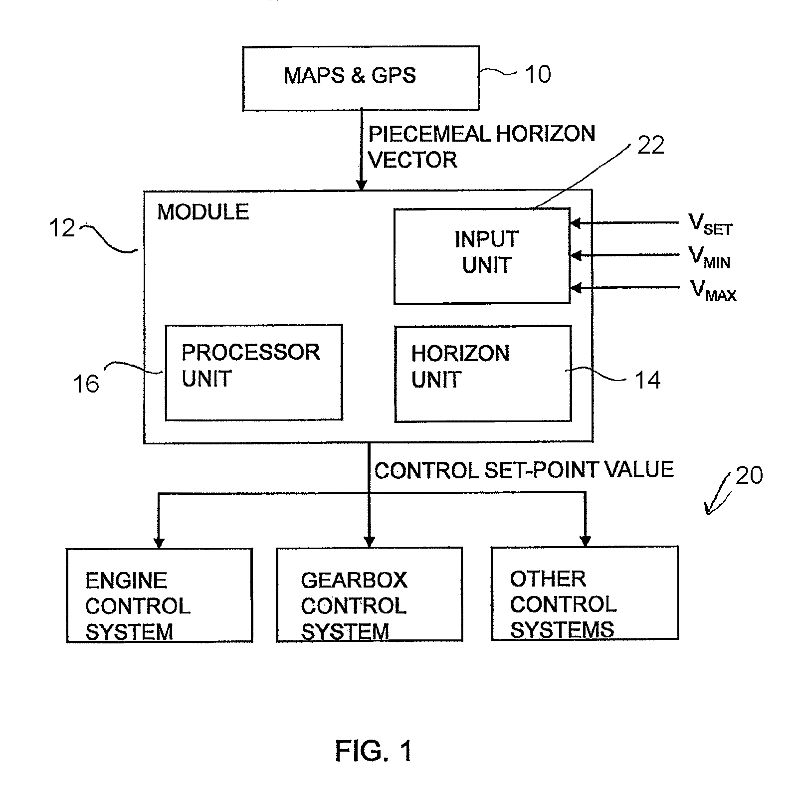
[0018]The regulating system according to the invention makes it possible to minimise the amount of fuel needed during the vehicle's journey by taking information about the itinerary into account. Map data, e.g. in the form of a database on board the vehicle with altitude information, and a positioning system, e.g. GPS, provide information about road topography along the itinerary. The control system is thereafter supplied with set-point values and regulates the vehicle according to them.
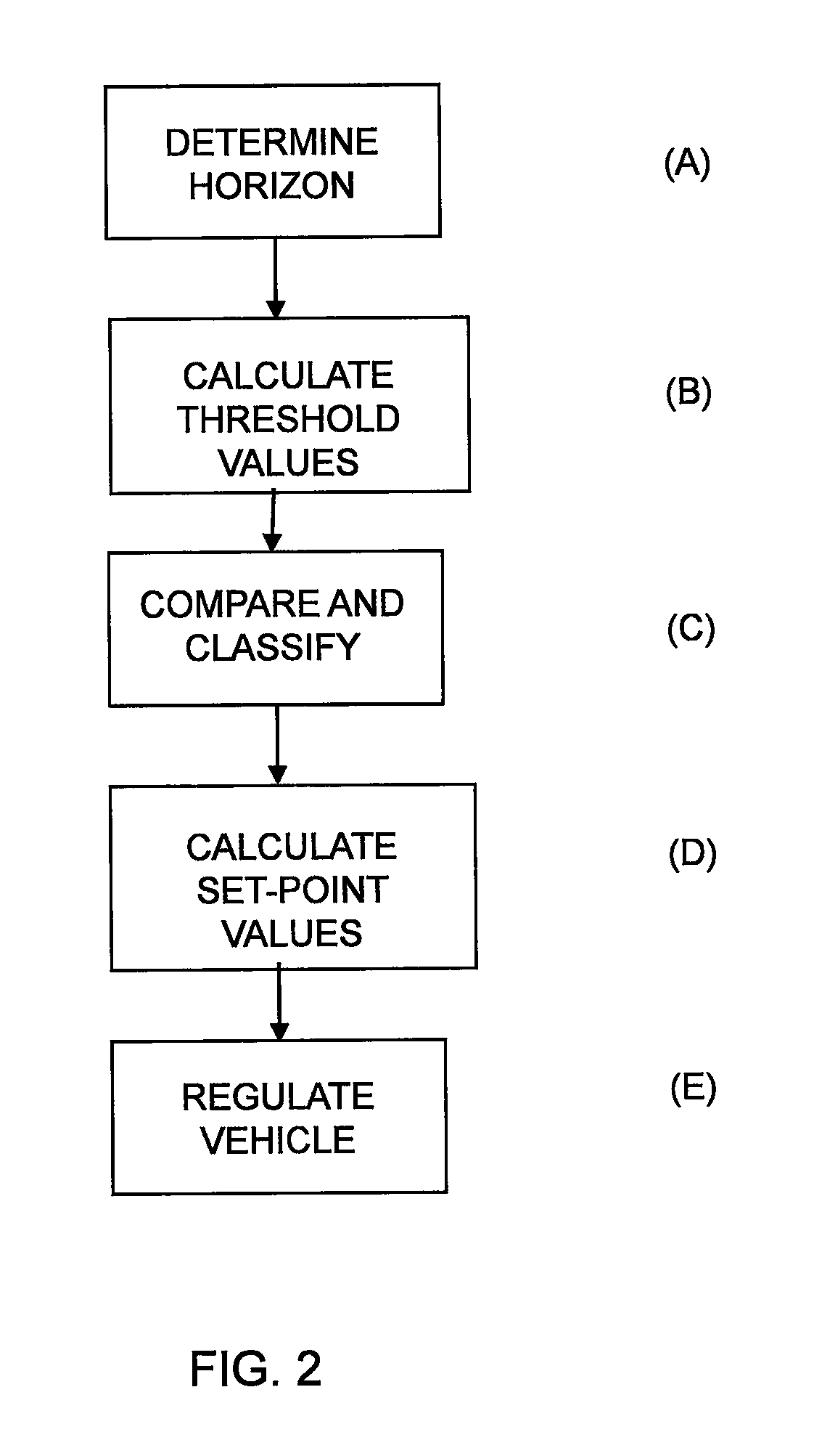
[0019]Using a system that practices a rule-based method results in a predictable robust method which can quickly calculate set-point values for the control system or control systems in the vehicle.

Problems solved by technology

This results inter alia in the vehicle accelerating over the crest of a hill and possibly into a subsequent downgrade, making it necessary to brake to avoid exceeding the set speed, which is a fuel-expensive way of running the vehicle.
A problem is that it is difficult for the control system to determine how much the cruise control should be allowed to vary the speed.
Generally speaking, a larger speed range results in more fuel saving, but also large speed variations, which may be disturbing to other traffic.
However, the specification gives no details about how this is done in practice.

Method used


Image

  • Module for determining of reference values for a vehicle control system
  • Module for determining of reference values for a vehicle control system
  • Module for determining of reference values for a vehicle control system

Examples


Embodiment Construction

[0026]Information about a vehicle's itinerary can be used to regulate its set-point speed vref for vehicle control systems, for example, the cruise control in the vehicle, in anticipation, for example, of topology in the horizon of the vehicle in order to save fuel, increase safety and enhance comfort. Other set-point values for other control systems may also be regulated. Topology greatly affects the control of, in particular, the driveline of heavy vehicles, since much more torque is required uphill than downhill and to make it possible to climb some hills without changing gear.

[0027]The vehicle is provided with a positioning system and map information, and position data from the positioning system and topology data from the map information are used to construct a horizon which illustrates the nature of the itinerary. In the disclosure hereof, GPS (Global Positioning System) is indicated for determining position data for the vehicle, but it should be appreciated that other kinds o...


PUM


Abstract

A module for determination of speed set-point values vref for a vehicle's control systems, comprising an input unit adapted to input, e.g., by the vehicle's driver, of a reference speed vset which is the speed desired by the driver for the vehicle. The module includes a horizon unit to determine a horizon by means of received position data and map data of an itinerary made up of route segments with at least one characteristic for each segment; a processor unit to calculate vref for the vehicle's control systems across the horizon according to rules pertaining to categories in which segments within the horizon are placed, so that vref is within a range bounded by vmin and vmax, where vmin≦vset≦Vmax, which control system regulates the vehicle according to these set-point values.

Description

CROSS-REFERENCE TO RELATED APPLICATIONS[0001]The present application is a 35 U.S.C. §§371 national phase conversion of PCT / SE2010 / 050590, filed May 31, 2010, which claims priority of Swedish Application No. 0950436-6, filed Jun. 10, 2009, the contents of which are incorporated by reference herein. The PCT International Application was published in the English language.FIELD OF THE INVENTION[0002]The present invention relates to a module for determining set-point values of vehicle speed for a control system in a vehicle.BACKGROUND TO THE INVENTION[0003]Many vehicles today are equipped with a cruise control to make it easier for the driver to drive the vehicle. The desired speed can then be set by the driver, e.g. via a control device in the steering wheel console, and a cruise control system in the vehicle thereafter regulates for example the vehicle's engine so that the desired speed can be maintained. If the vehicle is equipped with an automatic gear change system, the vehicle's ge...

Claims


Application Information

Patent Timeline
Patent Type & Authority Patents(United States)
IPC IPC(8): B60T8/32B60W30/14B60W40/06
CPCB60W30/143B60W40/06B60W2550/142B60W2550/402B60W2720/103Y02T10/56B60W30/16B60W50/0097B60W2552/15B60W2552/20B60W2554/801B60W2554/804B60W2556/50Y02T10/40Y02T10/84B60K31/00
Inventor JOHANSSON, OSKARHANSSON, JORGENPETTERSSON, HENRIK
Owner SCANIA CV AB
Learn More