Driving control device, method, and non-transitory storage medium

a technology of driving control device and non-transitory storage medium, which is applied in the direction of driver input parameters, external condition input parameters, transportation and packaging, etc., can solve the problem of not being able to quantitatively predict the amount of regenerative energy recovery, and achieve the effect of reducing the amount of fuel predicted to be consumed and reducing the energy loss of the electric motor

Pending Publication Date: 2022-04-28
TOYOTA JIDOSHA KK
View PDF1 Cites 1 Cited by
  • Summary
  • Abstract
  • Description
  • Claims
  • Application Information

AI Technical Summary

Benefits of technology

[0009]In the driving control device according to the first aspect of the present disclosure, the processor may be configured to determine the first time and the second time so as to minimize an amount of fuel predicted to be consumed when the vehicle is caused to travel using the internal combustion engine in a region other than the first region and the second region. In the driving control device according to the first aspect of the present disclosure, the processor may be configured to set only the first region as the region in which the vehicle travels using the electric motor, when an amount of fuel predicted to be consumed when the vehicle is caused to travel using the internal combustion engine in a region other than the first region and the second region is larger than an amount of fuel predicted to be consumed when the vehicle is caused to travel using the internal combustion engine in a region other than the first region, and may be configured to set the first region and the second region as the region in which the vehicle travels using the electric motor, when the amount of fuel predicted to be consumed when the vehicle is caused to travel using the internal combustion engine in the region other than the first region and the second region is smaller than the amount of fuel predicted to be consumed when the vehicle is caused to travel using the internal combustion engine in the region other than the first region. In the driving control device according to the first aspect of the present disclosure, the processor may be configured to determine the first time and the second time based on the predicted amount of regenerative energy minus energy loss in the electric motor.
[0010]In the driving control device according to the first aspect of the present disclosure, the processor may be configured to determine the first time and the second time in such a manner that a maximum value of power that is generated by the electric motor in the first region and a maximum value of power that is generated by the electric motor in the second region become equal. In the driving control device according to the first aspect of the present disclosure, the processor may be configured to determine the first time and the second time in such a manner that priority is given to one of the first region and the second region, the one of the first region and the second region having smaller energy loss in the electric motor. In the driving control device according to the first aspect of the present disclosure, the processor may be configured to create the speed profile based on either or both of a driving history of a user and a driving history of a person other than the user.

Problems solved by technology

In the technique of Japanese Patent No. 4702086, it is possible to predict a point at which recovery of regenerative energy can be expected, but it is not possible to quantitatively predict the amount of regenerative energy recovery.

Method used


Image

  • Driving control device, method, and non-transitory storage medium
  • Driving control device, method, and non-transitory storage medium
  • Driving control device, method, and non-transitory storage medium

Examples


Embodiment Construction

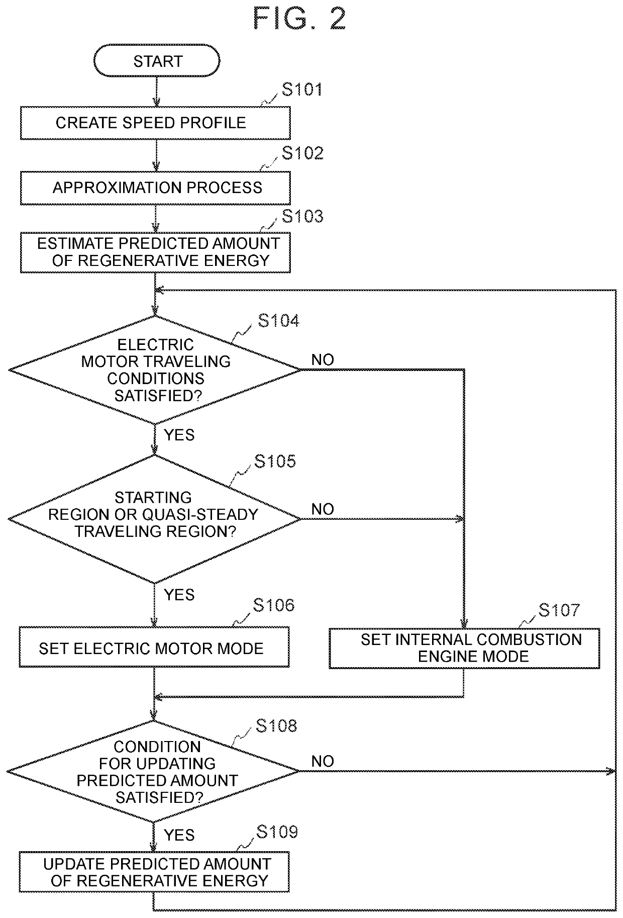
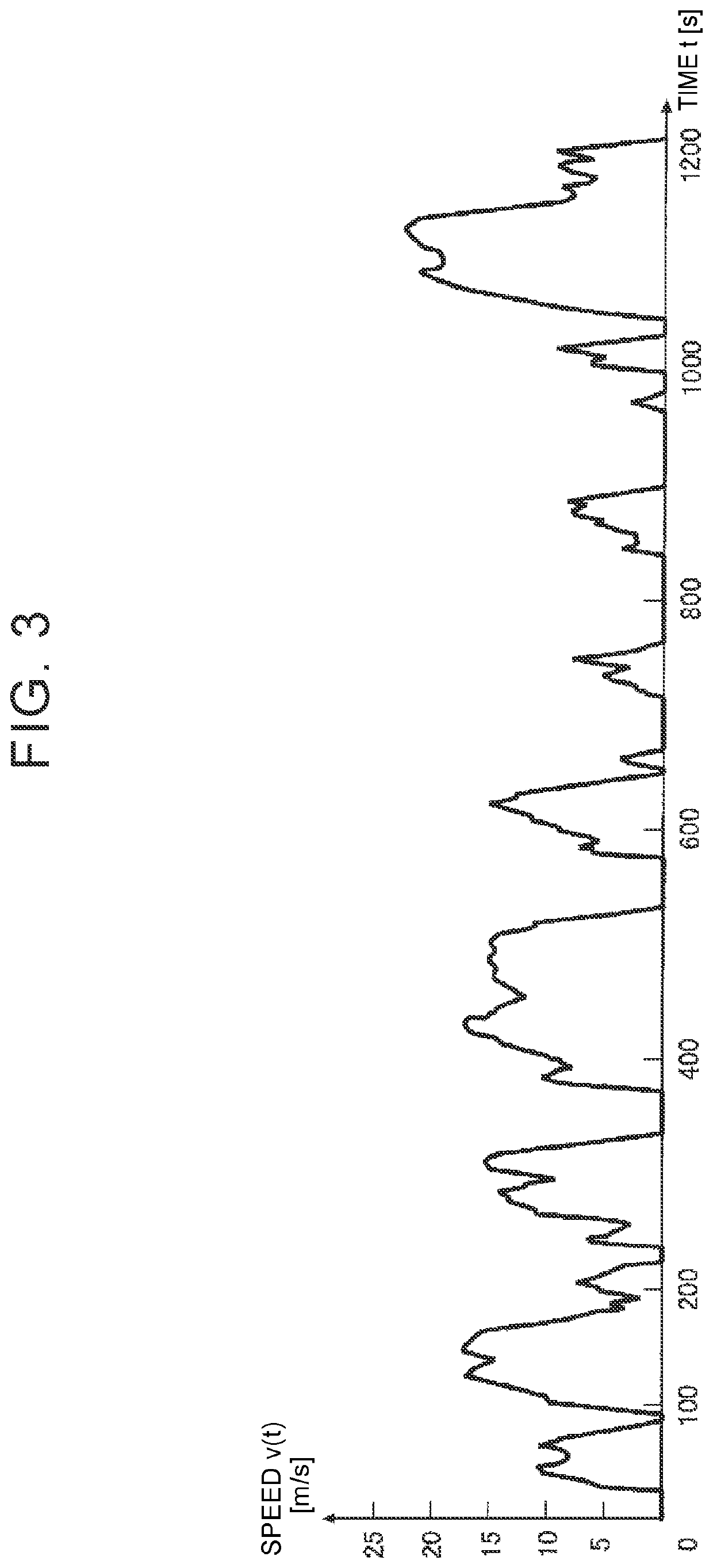
[0029]An embodiment of the present disclosure will be described with reference to the drawings. A driving control device according to the present embodiment performs suitable driving control for improved fuel efficiency by quantitatively predicting the amount of regenerative energy recovery at an early stage by using a speed profile that predicts the speed of a vehicle.

Configuration

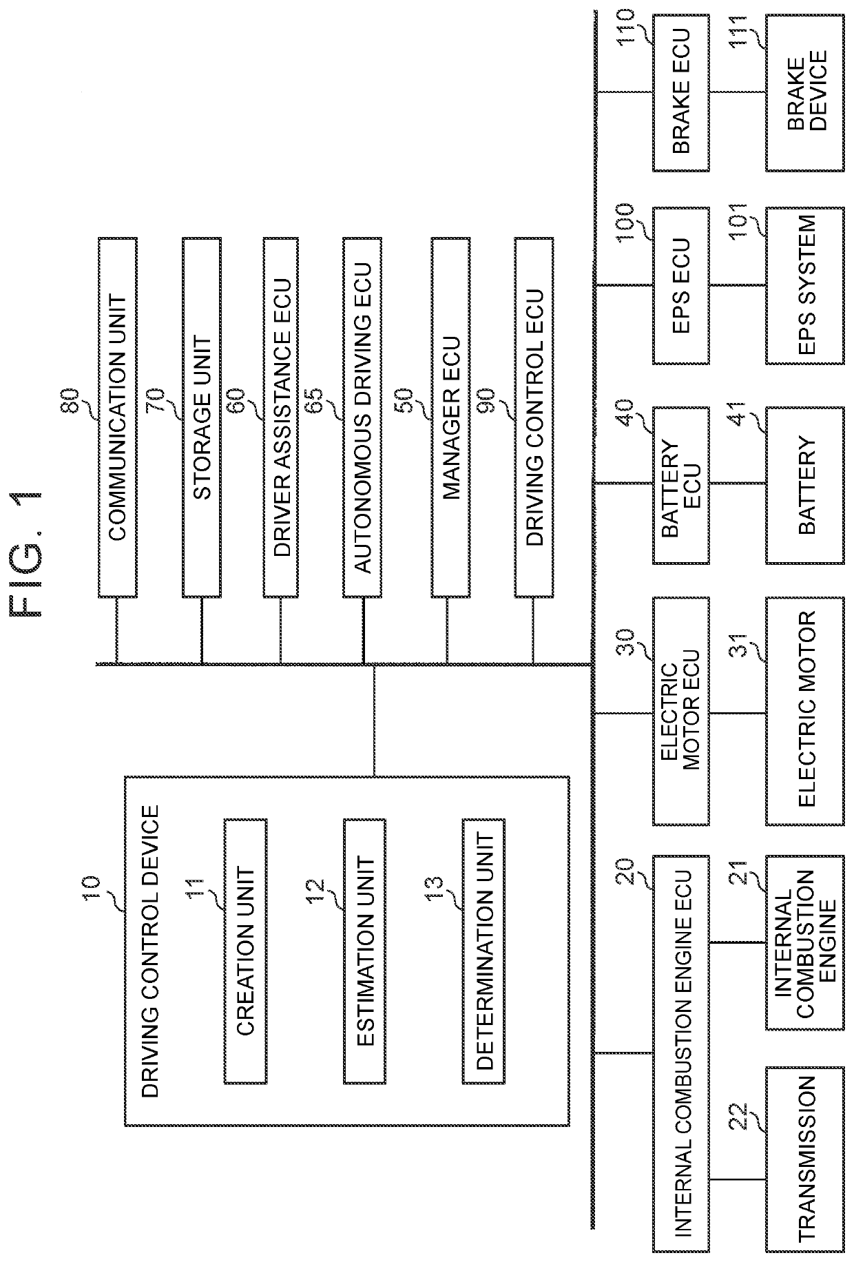
[0030]FIG. 1 illustrates functional blocks of a driving control device 10 and its peripheral components according to an embodiment of the present disclosure. The driving control device 10 is mounted on a vehicle. The vehicle includes, in addition to the driving control device 10, an internal combustion engine electronic control unit (ECU) 20, an internal combustion engine 21, a transmission 22, an electric motor ECU 30, an electric motor 31, a battery ECU 40, a battery 41, a manager ECU 50, a driver assistance ECU 60, an autonomous driving ECU 65, a storage unit 70, a communication unit 80, a driving cont...


PUM


Abstract

A driving control device mounted on a vehicle includes a processor. The processor is configured to create a speed profile. The processor is configured to approximate the speed profile by a predetermined approximate model and estimate a predicted amount of regenerative energy based on an approximation result. The processor is configured to set, based on the predicted amount of regenerative energy, a first region and a second region in the approximation result as a region in which the vehicle travels using an electric motor, the first region being a region from a timing of starting of the vehicle until first time has elapsed from the timing of starting of the vehicle, and the second region being a region from a timing of deceleration of the vehicle until second time has elapsed from the timing of deceleration of the vehicle.

Description

CROSS-REFERENCE TO RELATED APPLICATION[0001]This application claims priority to Japanese Patent Application No. 2020-178313 filed on Oct. 23, 2020, incorporated herein by reference in its entirety.BACKGROUND1. Technical Field[0002]The present disclosure relates to driving control devices that are mounted on vehicles, methods, and non-transitory storage media.2. Description of Related Art[0003]In a hybrid vehicle including an electric motor and an internal combustion engine, fuel efficiency can be improved by driving control in which the electric motor and the internal combustion engine are efficiently used according to the situation.[0004]Japanese Patent No. 4702086 discloses a vehicle driver assistance device that provides a user with a braking start point at which a regenerative braking operation needs to be started, based on the position of a vehicle and map information of points at which the vehicle needs to be stopped or points at which the vehicle needs to be decelerated such ...

Claims


Application Information

Patent Timeline
Patent Type & Authority Applications(United States)
IPC IPC(8): B60W10/08B60W10/18B60W20/11B60W20/20B60W30/18B60W40/105
CPCB60W10/08B60W10/18B60W20/11B60W2050/0028B60W30/18127B60W40/105B60W20/20B60W20/00B60W40/00B60W10/06B60W20/12B60W50/0097B60W2540/30B60W2556/10Y02T10/62Y02T10/70Y02T10/72B60W2720/103B60W2552/05
Inventor TOKURA, TAKAAKIKONO, KATSUMIYASUDA, TAKESHI
Owner TOYOTA JIDOSHA KK
Why Eureka
Try Eureka