System for directing air flow to a plurality of plena

a technology of air flow and system, applied in the direction of continuous jet plants, efficient propulsion technologies, machines/engines, etc., can solve the problem that the flow rate of the fan air that is redirected may not be sufficient to adequately cool the extracted air, and achieve the effect of reducing losses for conditions

Inactive Publication Date: 2015-06-02
HONEYWELL INT INC
View PDF25 Cites 23 Cited by
  • Summary
  • Abstract
  • Description
  • Claims
  • Application Information

AI Technical Summary

Problems solved by technology

During some operational levels of the turbofan engine, the flow rate of the fan air that is redirected may be insufficient to adequately cool the extracted air.

Method used


Image

  • System for directing air flow to a plurality of plena
  • System for directing air flow to a plurality of plena
  • System for directing air flow to a plurality of plena

Examples


Embodiment Construction

[0017]The following detailed description is merely exemplary in nature and is not intended to limit the invention or the application and uses of the invention. As used herein, the word “exemplary” means “serving as an example, instance, or illustration.” Thus, any embodiment described herein as “exemplary” is not necessarily to be construed as preferred or advantageous over other embodiments. All of the embodiments described herein are exemplary embodiments provided to enable persons skilled in the art to make or use the invention and not to limit the scope of the invention which is defined by the claims.

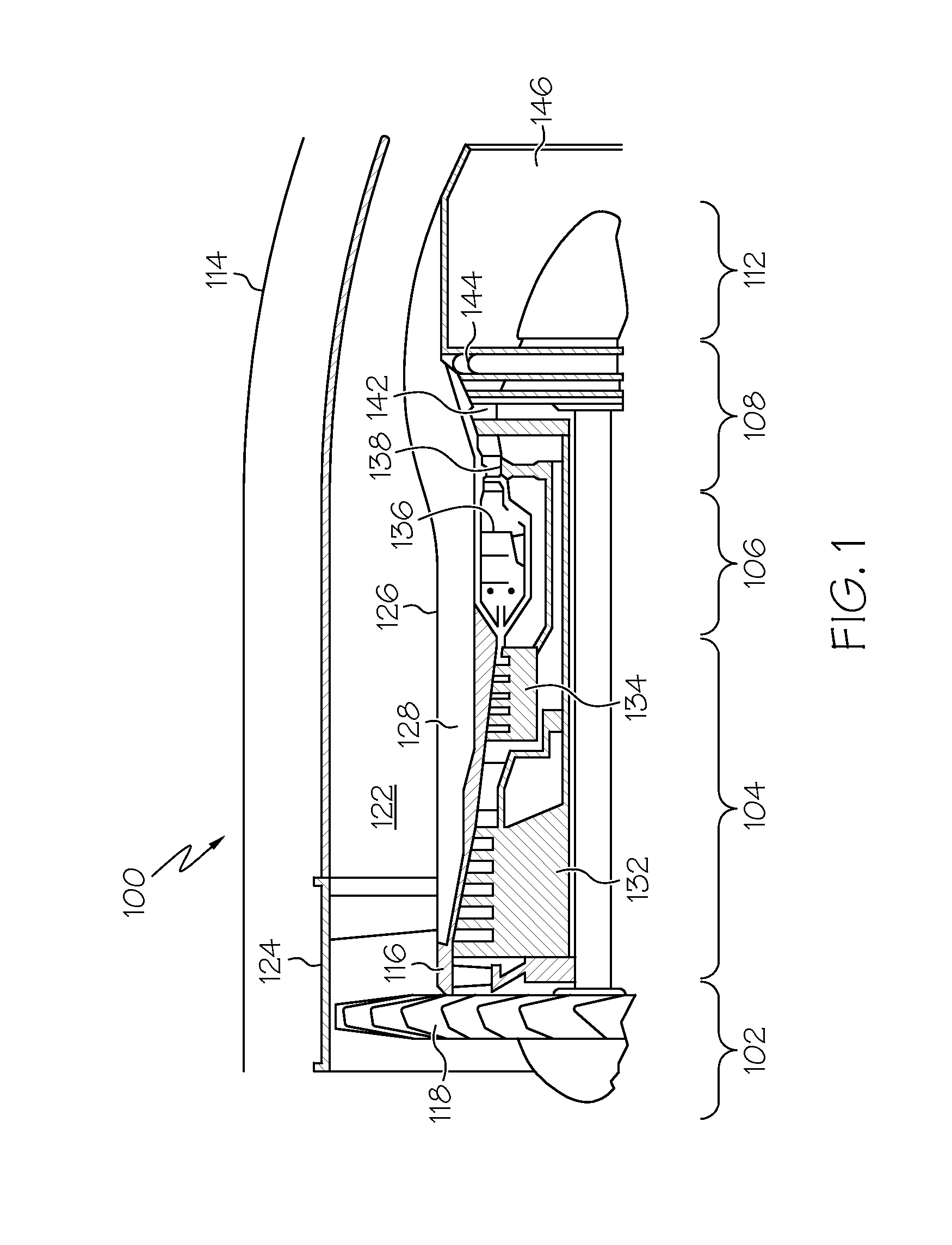
[0018]Furthermore, there is no intention to be bound by any expressed or implied theory presented in the preceding technical field, background, brief summary, or the following detailed description. In this regard, although the system for directing air flow that is described herein is done so in the context of a turbofan gas turbine propulsion engine, the system is not limited to thi...


PUM


Abstract

A system for directing air flow to separate plena of a compartment that is defined at least by a compartment wall includes a NACA scoop, and a Pitot scoop. The NACA scoop is formed in the compartment wall, and includes two side walls, a bottom wall, and an entrance lip that is defined by the compartment wall and is spaced apart from the bottom wall to form a NACA scoop air inlet. The Pitot scoop is longitudinally aligned with the NACA scoop, includes a Pitot scoop air inlet, a Pitot scoop air outlet, and a Pitot scoop flow passage.

Description

STATEMENT REGARDING FEDERALLY SPONSORED RESEARCH OR DEVELOPMENT[0001]This invention was made with Government support under FA8650-09-D-2925-003 awarded by the U.S. Air Force. The Government has certain rights in this invention.TECHNICAL FIELD[0002]The present invention generally relates to systems for directing air flow, and more particularly relates to a system for directing air flow to a plurality of plena, such as in a turbofan gas turbine propulsion engine.BACKGROUND[0003]In the field of gas turbine technology a great deal of effort has been, and continues to be, directed toward improving thermodynamic efficiency by operating gas turbine engines at ever increasing temperatures. These temperatures may exceed the temperatures that some materials within the turbine engine structure can normally tolerate. As such, cooling air may be provided to various turbine engine components using cooling air extracted from other parts of the engine. For example, in some gas turbine engines cooli...

Claims


Application Information

Patent Timeline
Patent Type & Authority Patents(United States)
IPC IPC(8): F02K7/08F02K7/10F01D17/10F02C7/141F02K3/075F02K3/115
CPCF01D17/105F02K3/115F02K3/075F02C7/141Y02T50/675F02C6/08Y02T50/60
Inventor LO, CHARLESALFORD, TEDANDERSON, MORRIS
Owner HONEYWELL INT INC
Why Eureka
Try Eureka