
Array of individually angled mirrors reflecting disparate color sources toward one or more viewing positions to construct images and visual effects

a technology of individual angled mirrors and color sources, applied in the direction of projectors, instruments, viewers, etc., can solve the problems of increasing technical difficulty, affecting the quality of images, so as to achieve the effect of different viewing area sizes

Active Publication Date: 2015-06-30
YETT JAMES
View PDF14 Cites 3 Cited by
  • Summary
  • Abstract
  • Description
  • Claims
  • Application Information

AI Technical Summary

Benefits of technology

The patent describes a new type of display that uses mirrors to create a unique visual effect. The colors in the display are not determined by the actual spots of pigment, but rather by the angles at which the mirrors are positioned. This allows for easy manipulation of the display's colors through computer programs. The display can also be controlled by live computer, making it more versatile and responsive to viewer position and changes in the environment. The reflectable color set can be a pre-existing random constellation of colors or an augmented random set, and can include a wide range of reflectable environmental characteristics. The display can also have different color source swatch sizes for different parts of the image, allowing for different viewing areas and effects. The patent also describes how to stabilize the viewer's gaze and how to notate the image attributes at different positions within the viewing area. Overall, the patent provides a new way to create visually stunning and engaging displays using mirrors and computer programming.

Problems solved by technology

The simplest class of angled mirror array image effects, effects configured without regard to colors in the viewing environment, includes image distortions akin to fun house mirror effects, but also such effects to a far more complex degree and with fewer mirror shape design constraints, partially because a mirror array considered as a distorting surface can have shape discontinuities not possible in a bent or even a folded continuous reflective sheet.
In some constructions very long form animation is possible—theoretically of arbitrary length and, with increasing technical difficulty, any resolution.
This moving images technique is possible using non-modern components, though animation of any length or resolution would be very labor intensive, without computer assistance in repeating the thousands of iterations required to set up each frame.
If no orange color sources exist in the environment of the reflective display, then it may not be possible in that location to reflectively construct an image of a tangerine, at least not an orange tangerine.
Display effects can be very complicated, and the reflective reference color maps required to produce them can therefore be very complex, large and elaborate.

Method used


Image

  • Array of individually angled mirrors reflecting disparate color sources toward one or more viewing positions to construct images and visual effects
  • Array of individually angled mirrors reflecting disparate color sources toward one or more viewing positions to construct images and visual effects
  • Array of individually angled mirrors reflecting disparate color sources toward one or more viewing positions to construct images and visual effects

Examples


Embodiment Construction

and OPERATION

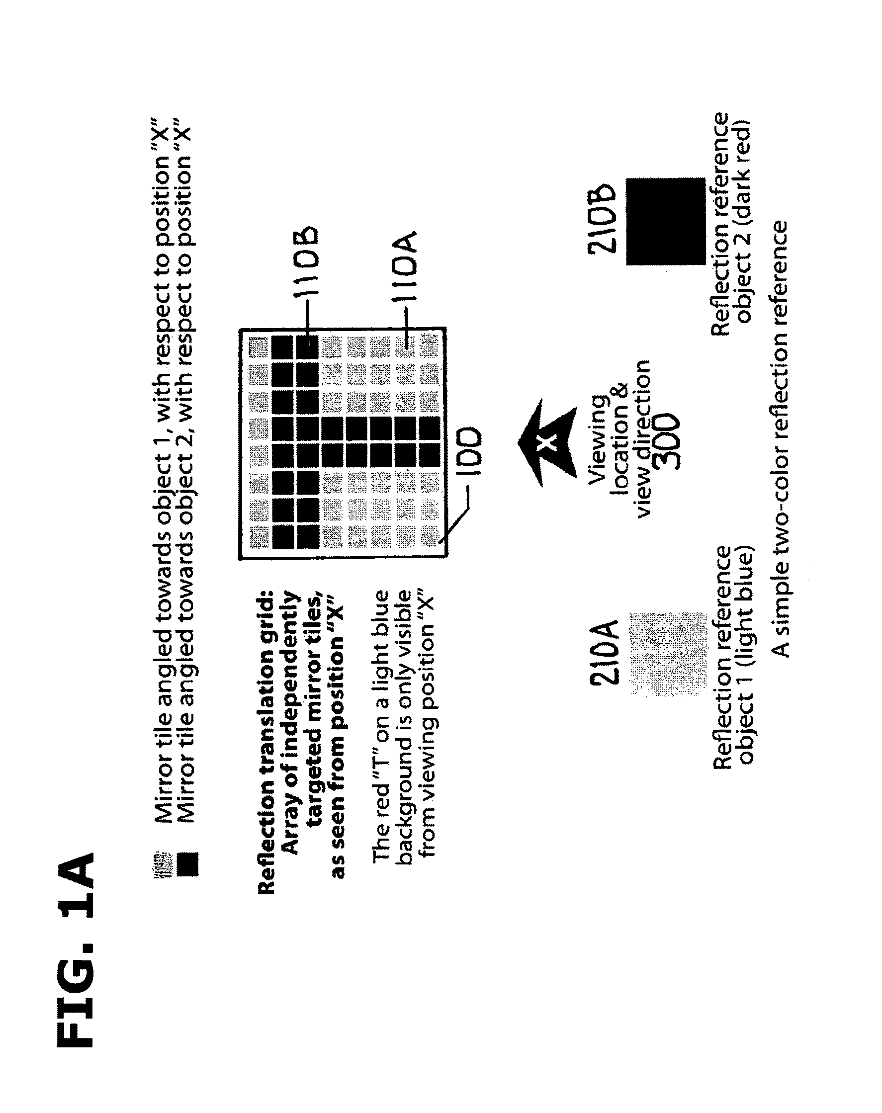
FIG. 1A: A Small Two-Color Reflectively Constructed Image

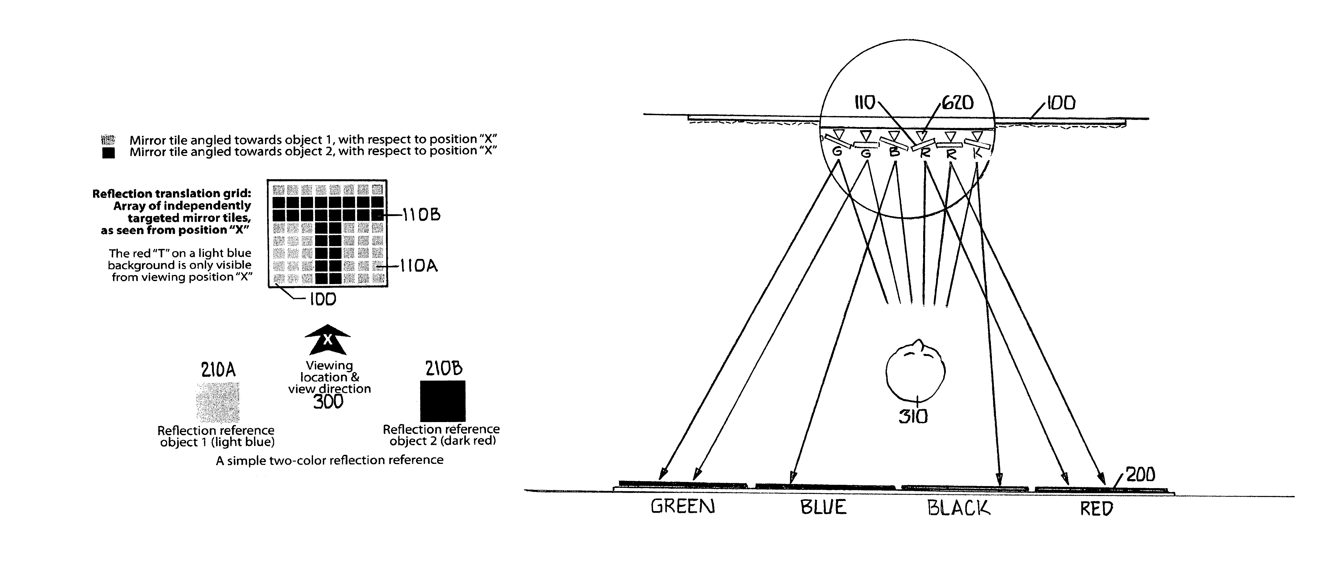
[0100]Referring now to the drawings, in FIG. 1A is shown a reflective array 100 in which each reflective element 110A and 110B reflects toward a viewing position 300 a reflection source color 210A or 210B. Each reflective element 110A or 110B can, by the art of the setting of its reflection angle, present to the viewer 300 either one of the two available reflectable colors 210A and 210B and thus the shown reflective array 100 can present images constructed of two colors, in this case the letter “T”. Additional reflectable colors can optionally be incorporated into more complex displays, allowing for images of greater color fidelity. Likewise, larger reflection arrays with more reflection elements can present more detailed, higher-resolution images.

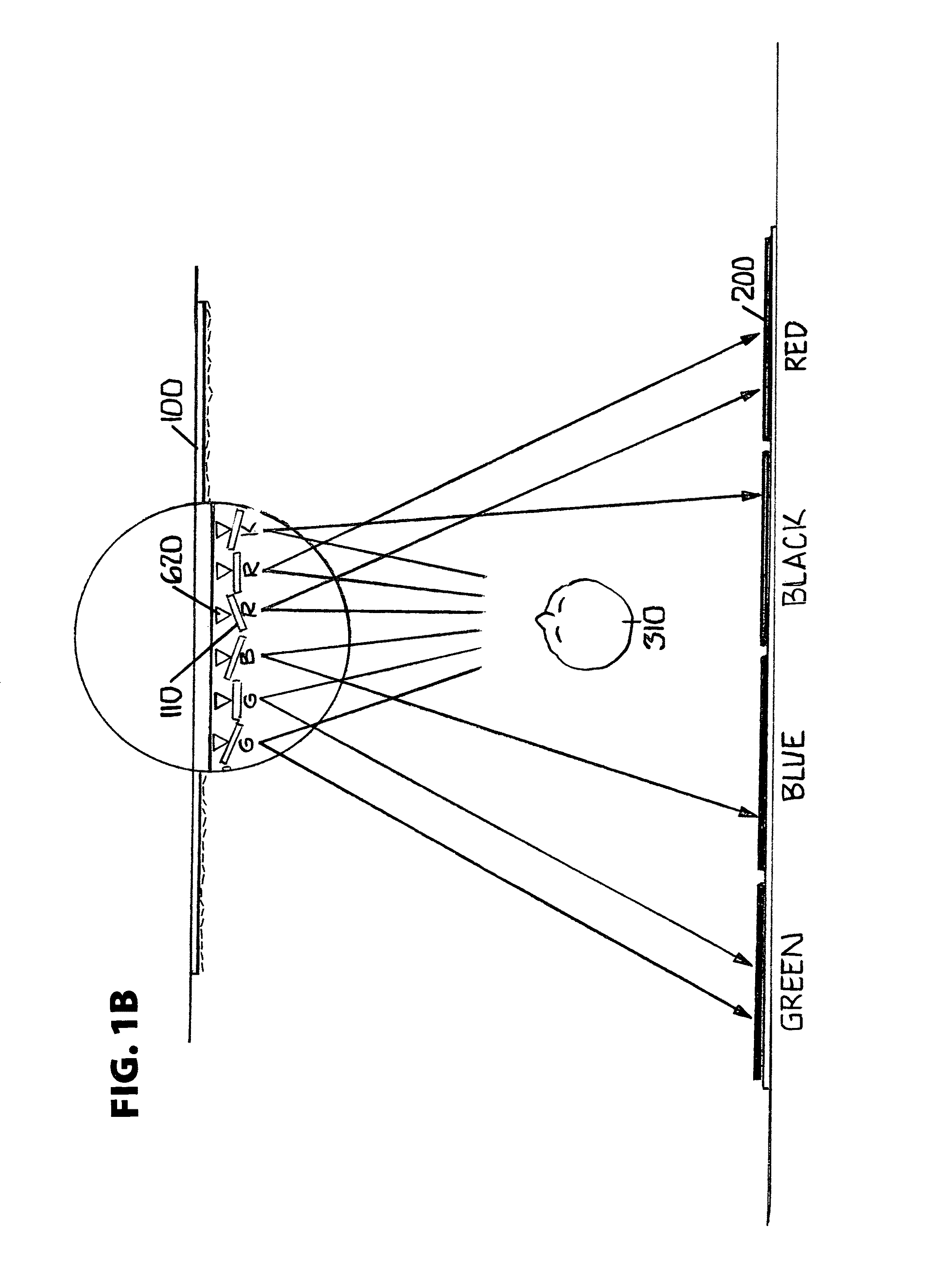
FIG. 1B: A Four-Color Reflectively Constructed Image

[0101]In FIG. 1B is shown a more detailed reflective array 100, with a much larger plurality of reflective elements 1...


PUM


Abstract

A general purpose image and visual effects display apparatus, with associated methods, which is comprised of an array of independently angled reflective or refractive elements wherein the varying angle pattern of each element across said array is designed to reflect or refract specifically designed as well as fortuitously located existing colors, in precisely determined patterns, to make apparent to specific viewing or receiving locations a wide range of complex emergent visual and other effects. In some embodiments very high resolution and high color fidelity image display is possible. In other embodiments moving images akin to video can be displayed, using no electronics or moving parts. In other embodiments true binocular 3D images can be displayed directly to viewers, without the need for special 3D viewing glasses. Many of the embodiments and methods are applicable to non-visible light and other reflectable wave-based phenomena.

Description

CROSS-REFERENCE TO RELATED APPLICATIONS[0001]This application claims the benefit of provisional patent application No. 61 / 214,564, filed Apr. 25, 2009 by the present inventor, which is incorporated by reference.FEDERALLY SPONSORED RESEARCH[0002]Not applicable.SEQUENCE LISTING OR PROGRAM[0003]Not applicable.BACKGROUND[0004]1. Field[0005]The invention relates to structures for representing full color images, animation, 3D graphics and other visual effects, and particularly to structures comprising a plurality of tile elements which reflect or refract light and the color reflection sources which are optionally organized in conjunction with or tracked and cataloged to be reflected by said array, to construct said visual effects.[0006]2. Prior Art[0007]U.S. Pat. No. 3,173,985, “Method of Reflection for Producing a Pleasing Image”, by Clifford A. Wendel, 1965, describes a method of producing a grey scale image on a screen by reflecting a light source onto a translucent screen using a face...

Claims


Application Information

Patent Timeline
Patent Type & Authority Patents(United States)
IPC IPC(8): G02B27/02G02B27/22H04N13/04
CPCH04N13/042G02B27/2235G02B27/022H04N13/322G02B30/35G02B26/0816G03B25/02G02B27/0093
Inventor YETT, JAMES
Owner YETT JAMES
Learn More