Connector

a technology of connecting rods and connectors, applied in the field of connecting rods, can solve the problems of affecting the service life of the patient, so as to achieve the effect of simple configuration, efficient discharge of stagnant fluid, and simplified connection of the connector

Active Publication Date: 2015-07-28
TERUMO KK
View PDF7 Cites 42 Cited by
  • Summary
  • Abstract
  • Description
  • Claims
  • Application Information

AI Technical Summary

Benefits of technology

[0013]With the above configuration, since the wall surface which directs fluid to the connection side space so as to flow toward at least one of the side parts, the fluid can be guided so that turbulence of stagnating fluid existing inside the connection side space is made large to accelerate the flow. Therefore, fluid stagnating inside the connection side space can be easily discharged from the connection side space by the fluid guided by the wall surface. As a result, when constructing an infusion line which administers an infusion fluid using the connector, the safety of fluid infusion can be significantly enhanced, and a desired infusion fluid can be excellently supplied to a patient.
[0024]According to embodiments of the present invention, it is possible to efficiently discharge fluid stagnating in a connection side space in a connection terminal from the connection side space with a simple configuration, thereby enhancing the safety of fluid infusion and excellently supplying a desired fluid.

Problems solved by technology

Such fluid stagnating in the connection side space (hereinbelow, also referred to as stagnating fluid in order to distinguish it from fluid flowing in the main line flow path) may disadvantageously cause various troubles, in particular, in medical instruments.
However, air bubbles (air) may stagnate in a connection side space of a connector.
As a result, when supplying the infusion fluid to the patient, the air bubbles remaining therein may be disadvantageously introduced into the patient together with the infusion fluid.
In addition, when supplying a high nutritive liquid as an infusion fluid, the liquid stagnates inside the connection side space, and bacteria may thereby grow inside the connector.
As a result, the bacteria may be disadvantageously introduced into a patient.
Further, when changing an infusion fluid supplied to a patient to a next infusion fluid, if the next infusion fluid is supplied with the previously supplied infusion fluid stagnating in the connection side space, these different infusion fluids may be disadvantageously mixed and introduced into a patient.
However, even when the wall is provided in a midway part of the main line flow path, and an infusion fluid is thereby guided to the connection side space as in the connector of JP 2010-505551, the infusion fluid is mixed into stagnating fluid that is previously filled inside the connection side space, and it is therefore difficult to discharge the stagnating fluid.
Therefore, the stagnating fluid still remains left in the connection side space, and the above troubles may occur.

Method used


Image

  • Connector
  • Connector
  • Connector

Examples


first embodiment

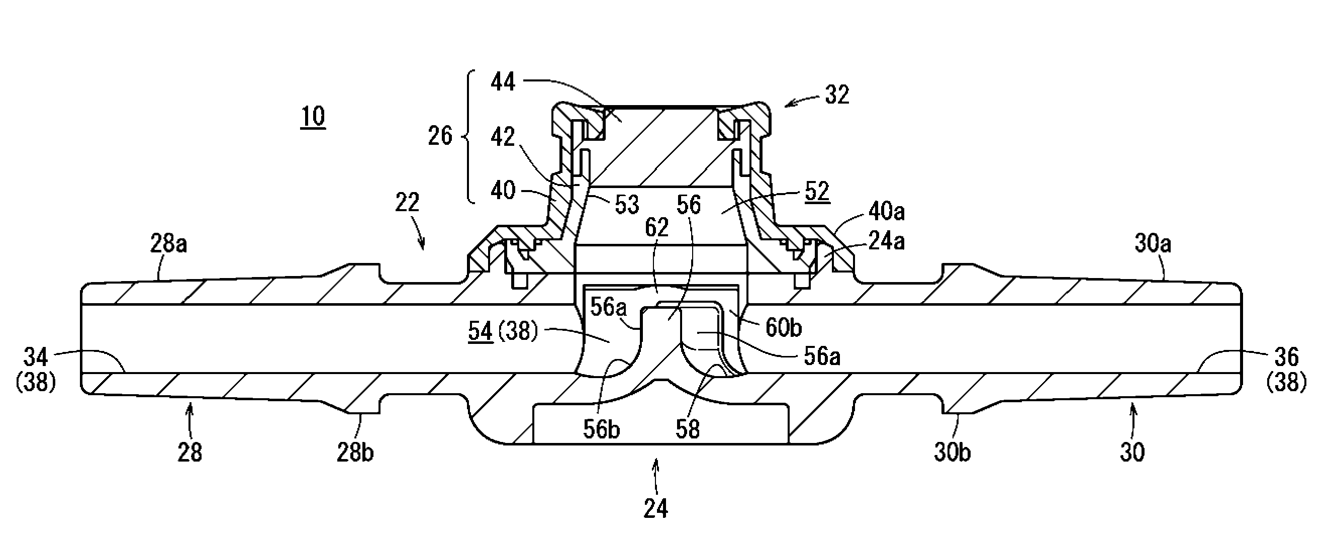
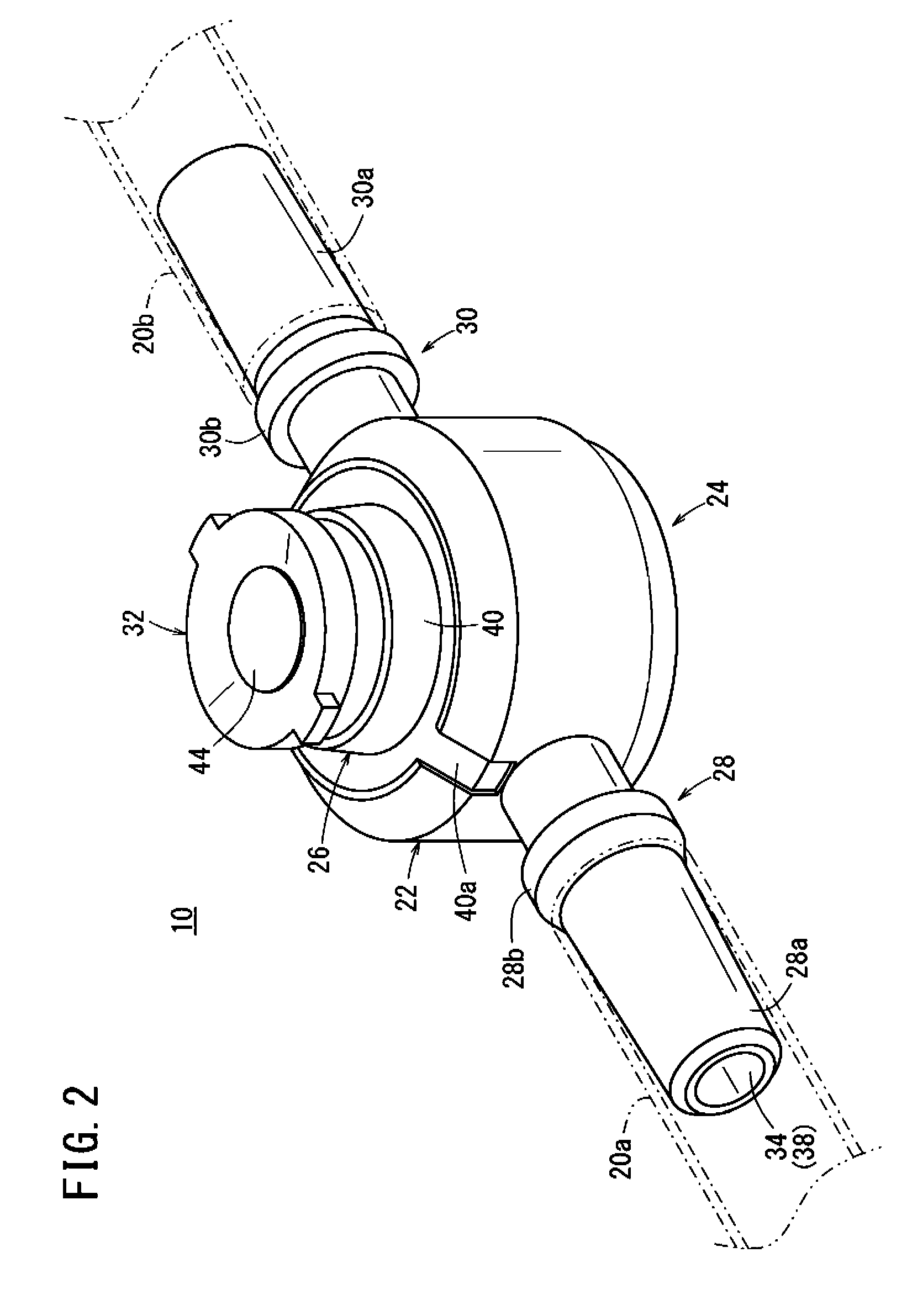
[0043]FIG. 2 is a perspective view illustrating the entire configuration of the connector 10 according to the first embodiment. FIG. 3 is a perspective view illustrating the connector 10 of FIG. 2 with a lid 26 detached therefrom. FIG. 4 is a plan view of the connector 10 of FIG. 3. FIG. 5 is a side cross-sectional view of the connector 10 of FIG. 2.

[0044]As illustrated in FIG. 2, the connector 10 includes a housing 22 which has a flow path of an infusion line (including a main line and auxiliary line) formed inside thereof. The housing 22 is formed of a resin material that is hard relative to the tube 20 having flexibility. Examples of the constituent material of the housing 22 include polyethylene, polypropylene, polyolefin such as ethylene-vinyl acetate copolymers, polyurethane, polyamide, polyester, polycarbonate, polybutadiene, and polyvinyl chloride.

[0045]The housing 22 includes a connector base 24 having a bottomed tubular shape, the lid 26 which is attached to the connector ...

second embodiment

[0085]FIG. 8 is a plan view illustrating the entire configuration of the connector 10A according to the second embodiment. In the connector 10A according to the second embodiment described below, the same configurations or configurations achieving the same functions as those of the connector 10 according to the first embodiment will be denoted by the same reference numerals, and description of these configurations will be omitted.

[0086]The connector 10A according to the second embodiment is different from the connector 10 according to the first embodiment in that the shape of a rib 70 is formed into a generally cross shape which is different from the shape of the rib 56. More specifically, the rib 70 of the connector 10A is provided in a standing manner on a bottom part 58 of a main line flow path 38, and has a top part 72 located on the central axis of the main line flow path 38 in plan view. A wall surface 70a of the rib 70 is formed so as to obliquely extend from the top part 72 ...


PUM


Abstract

A connector comprises a housing; a main flow path being configured such that fluid is flowable from a first tube through the main flow path into a second tube; and a connection terminal including a connection side space, the connection terminal being configured such that a third tube is connectable to the connection terminal and an auxiliary flow path of the third tube communicates with the main flow path via the connection side space. The main flow path includes a main flow path side space that is continuous with at least the connection side space and is defined by: a bottom part facing the connection side space and a pair of side parts extending from opposite sides of the bottom part toward the connection side space, and at least one wall surface configured to direct the fluid toward the connection side space and toward at least one of the side parts.

Description

CROSS-REFERENCE TO RELATED APPLICATIONS[0001]This application is a continuation application filed under 35 U.S.C. 111(a) claiming the benefit under 35 U.S.C. §§120 and 365(c) of PCT International Application No. PCT / JP2012 / 071041 filed on Aug. 21, 2012, which is based upon and claims the benefit of priority of Japanese Application No. 2011-210214 filed on Sep. 27, 2011, the entire contents of which are hereby incorporated by reference in their entireties.BACKGROUND[0002]1. Technical Field[0003]The present disclosure relates to a connector that connects a plurality of tubes to each other, for example, in an infusion line for performing fluid infusion to a patient.[0004]2. Background Art[0005]Conventionally, when performing fluid infusion to a patient, a plurality of tubes are connected to construct an infusion line which is continuous from an infusion bag as a supply source of an infusion fluid up to the patient, and a connector is used as a tool for connecting the tubes to each othe...

Claims


Application Information

Patent Timeline
Patent Type & Authority Patents(United States)
IPC IPC(8): A61M25/16A61M39/02A61M39/10A61M25/18A61M39/00
CPCA61M39/10A61M39/02A61M2206/14A61M2206/20
Inventor UEDA, YASUHIROZUSHI, YASUNOBU
Owner TERUMO KK
Why Eureka
Try Eureka