
Jack and dolly assembly and system

a technology of dolly and assembly, which is applied in the direction of mobile jacks, hand carts with multiple axes, lifting devices, etc., can solve the problems of inconvenient operation, inefficient mode of implementation, and frequent servicing of dolly

Active Publication Date: 2015-08-11
MOTIS LLC
View PDF11 Cites 8 Cited by
  • Summary
  • Abstract
  • Description
  • Claims
  • Application Information

AI Technical Summary

Benefits of technology

The invention relates to a jack and dolly assembly for lifting the wheels of a vehicle and allowing it to move in any direction of a single plane. The assembly consists of two arms that are actuated by a gear mechanism. This mechanism allows for easy reconfiguration of the lifting arms and gear mechanism. The assembly also features caster wheels and a roller sleeve for smooth movement of tires or wheels. Additionally, the assembly has a reversible drive mechanism and an adjustable position for the proximal arm. The technical effects of this invention include improved efficiency, flexibility, and safety during vehicle movement.

Problems solved by technology

The dollies currently presented by the prior art are inconvenient for many reasons.
The prior art exemplifies such means as requiring inefficient modes of implementation.
These structures comprise the use of an excessive amount of mechanical parts, require frequent servicing, and are bulky and difficult to operate.
Prior art devices also use greasy lubricants that leave not only themselves, but residual surfaces undesirable, dirty, and slippery.
Wheel dollies as taught in the prior art are often bulky, heavy, and difficult to transport and operate.
Another reoccurring experience is the position of a wheel such that the lifting mechanism cannot be accessed or easily actuated.
Often the lifting mechanism is too complicated to easily and timely effect actuation.
In all such situations, the dollies of the prior art require time consuming procedures.
Frequently, the user finds themselves forced into maneuvering their bodies into undesirable positions while placing the dolly and operating the lifting mechanism.
These circumstances lead to the frequent inability to properly and easily lift a wheel, and often lead to the misfortune of the jack and dolly assemblies being abandoned altogether.
However, the dollies found in prior art lack the ability to allow a user in this setting to place and actuate the device with ease; complicated actuation mechanisms force users to struggle while attempting to lift the vehicle onto the assembly.

Method used


Image

  • Jack and dolly assembly and system
  • Jack and dolly assembly and system
  • Jack and dolly assembly and system

Examples


Embodiment Construction

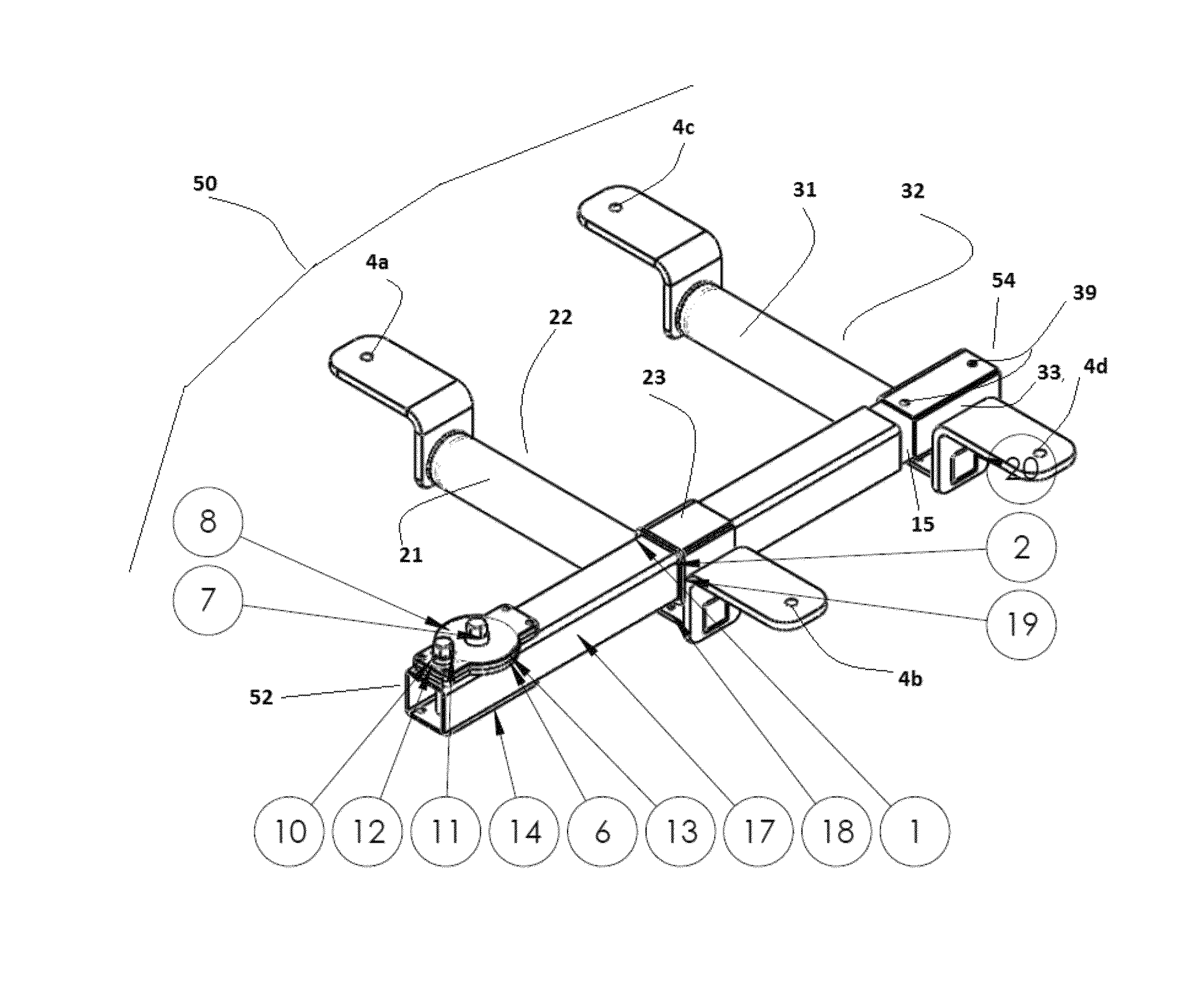
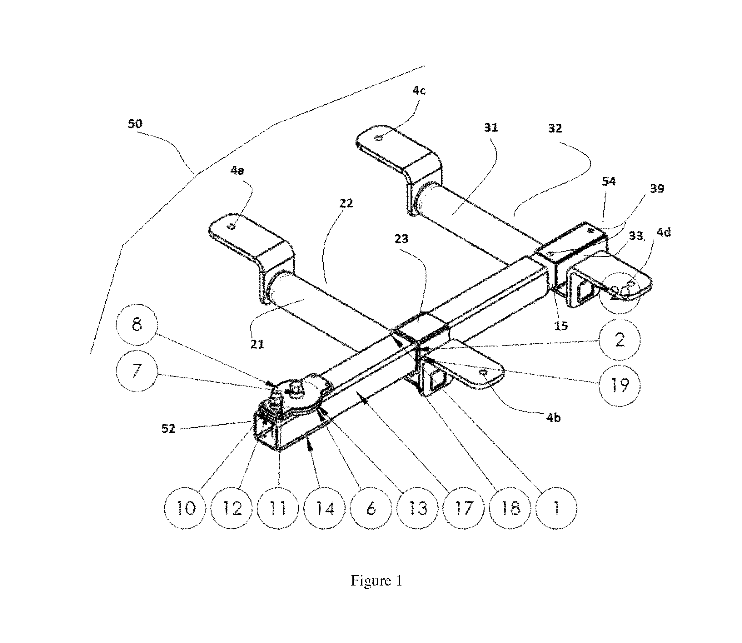
[0042]Referring now to the drawings in greater detail, and more particularly to FIG. 1, a modular jack and dolly assembly 50 for lifting and moving vehicles in a fashion similar to that of a dolly.

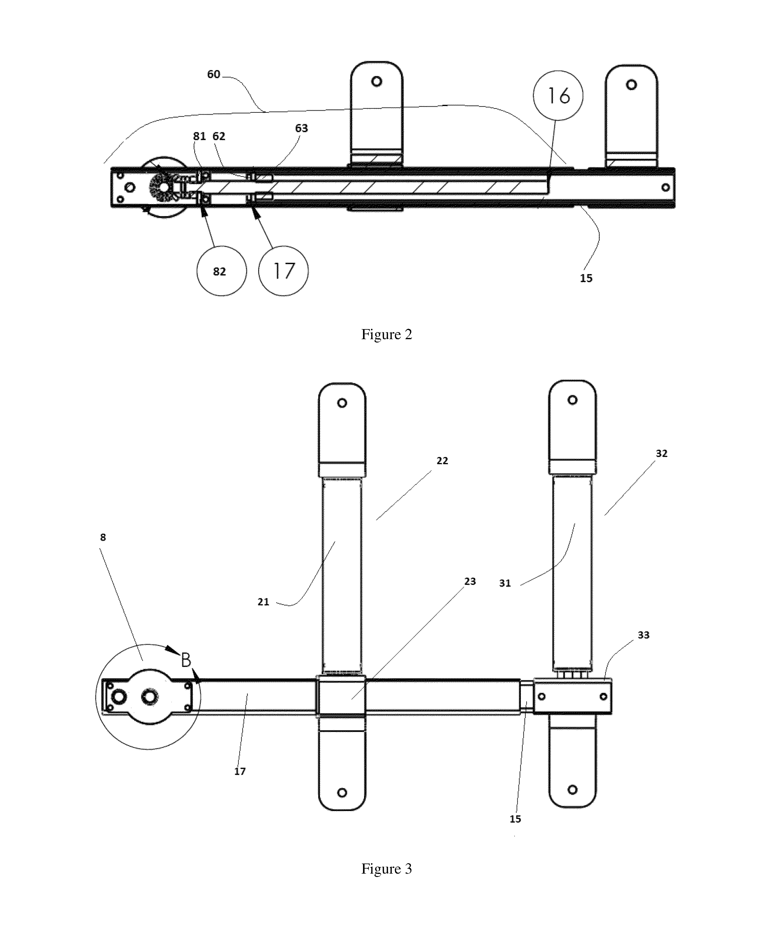
[0043]In at least one embodiment the jack and dolly assembly 50 as shown in FIGS. 1 and 2 included is a main support shaft 17 having a longitudinal axis extending along the shaft from the proximal end 52 to the distal end 54. The shaft encloses drive mechanism 60. A proximal arm 22 is removably securable to the shaft 17. Proximal arm 22 is secured in an adjacent position to shaft 17. A distal arm 32 is removably secured to the drive mechanism 60, and is secured in a position adjacent to shaft 17. Proximal arm 22 and distal arm 32 are secured about shaft 17 such that both arms are extending in the same adjacent direction with respect to the longitudinal axis of the main shaft 17.

[0044]In one embodiment of the present invention, the jack and dolly assembly 50 is shown in FIGS. 1 and 2. Inclu...


PUM


Abstract

A jack and dolly assembly and system including a shaft defining a longitudinal axis extending along the shaft and an interior hollow; a reversible drive mechanism at least partially positioned in the interior hollow of the shaft; a proximal arm removably securable to the shaft and substantially perpendicular to the longitudinal axis; a distal arm removably securable to the drive mechanism, the distal arm being spaced from and substantially parallel to the proximal arm; wherein the reversible drive mechanism is operable to move the distal arm along the shaft.

Description

CROSS REFERENCE TO RELATED APPLICATIONS[0001]This application claims the benefit of U.S. Provisional Application Ser. No. 61 / 718,826, filed Oct. 26, 2012, the complete subject matter of which is incorporated herein by reference in its entirety.FIELD OF THE INVENTION[0002]The invention relates to a jack and dolly assembly for lifting the wheel(s) of a vehicle. More particularly, the invention relates to a modular jack and dolly assembly for the lifting and subsequent moving of a vehicle while suspended upon the jack and dolly assembly. The assembly allows for the vehicle to be moved about an infinite number of axes in a single plane.BACKGROUND OF THE INVENTION[0003]Dollies for lifting and moving vehicles are well known in the art. Commonly, wheel dollies are used in the industry across various settings including towing and vehicle recovery, and also in repair and mechanical shop venues. The dollies currently presented by the prior art are inconvenient for many reasons.[0004]It is kno...

Claims


Application Information

Patent Timeline
Patent Type & Authority Patents(United States)
IPC IPC(8): B62B3/02
CPCB62B3/02Y10T74/18576B66F7/246B62B3/0612B66F5/02B66F5/025
Inventor HEINZ, RICHARD N.
Owner MOTIS LLC
Learn More