

Automatic tool marking
a tool and marking technology, applied in the field of invasive medical procedures, can solve problems such as the failure of the tracking system
- Summary
- Abstract
- Description
- Claims
- Application Information
AI Technical Summary
Benefits of technology
Problems solved by technology
Method used
Image

Examples
first embodiment
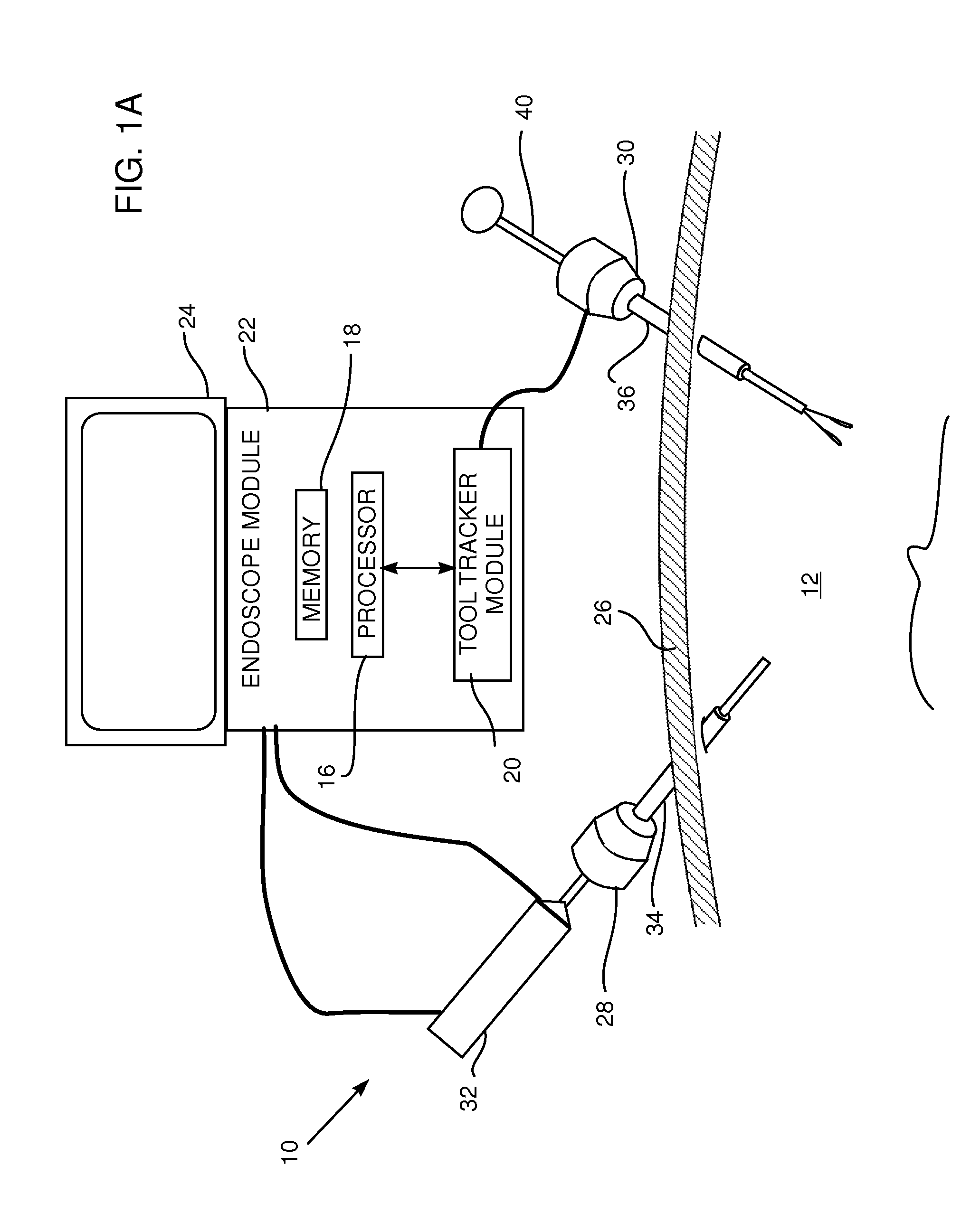
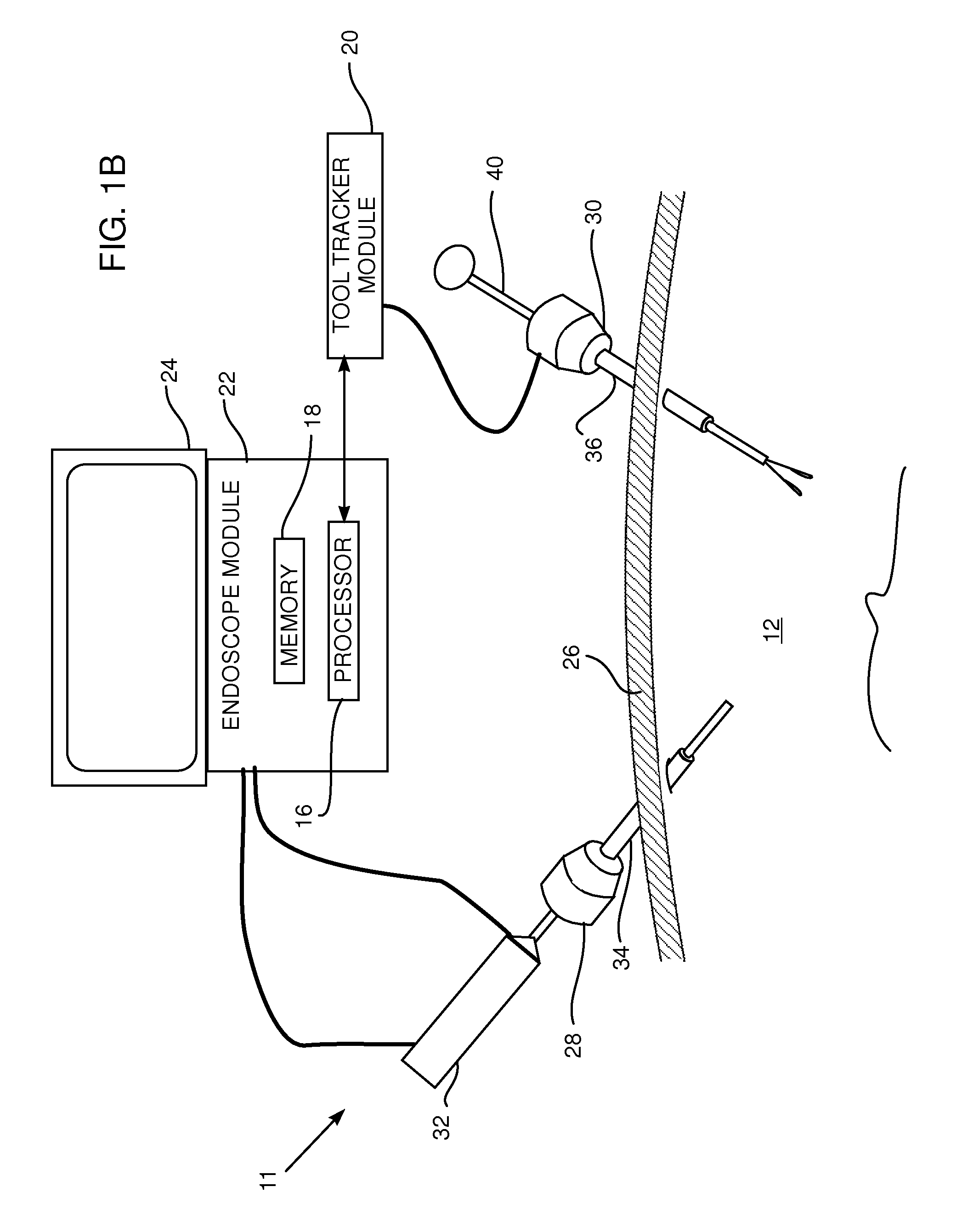
[0035]FIGS. 2A and 2B are schematic cross-sectional illustrations of trocar 30, according to the present invention. FIG. 2A illustrates the trocar before tool 40 passes through tubular member 36 of the trocar. FIG. 2B illustrates the trocar while the tool is passing through tubular member 36, and when a distal end 42 of tool 40 projects beyond a distal end 44 of the trocar. By way of example, in the description herein tubular member is assumed to be cylindrical, with an axis of symmetry 37. Optical elements (described in more detail below) that are located at the distal end of trocar 30 are connected to, and controlled by, tool tracker module 20. For clarity, the connections, typically comprising optical and / or conductive cables, are not shown in the figures. In some embodiments at least some of the connections may comprise wireless connections.
[0036]At its distal end 44, trocar 30 comprises at least one illuminator 46 emitting radiation beyond the distal end of the tubular member. ...
second embodiment
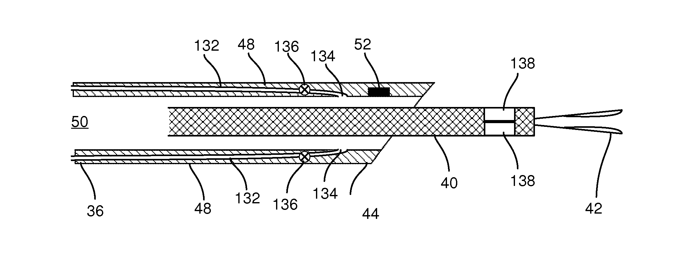
[0045]FIGS. 3A and 3B are schematic cross-sectional illustrations of a trocar 130, according to the present invention. Apart from the differences described below, the operation of trocar 130 is generally similar to that of trocar 30 (FIGS. 1, 2A and 2B), and elements indicated by the same reference numerals in both trocars 30 and 130 are generally similar in construction and in operation. FIG. 3A illustrates trocar 130 before tool 40 passes through tubular member 36 of the trocar. FIG. 3B illustrates trocar 130 while the tool is passing through tubular member 36, and when distal end 42 of tool 40 projects beyond distal end 44 of the trocar.
[0046]In contrast to trocar 30, trocar 130 does not have illuminators 46 to act as an indicator. Rather, distal end 44 of trocar 130 comprises one or more generally similar tubes 132 within wall 48, the tubes exiting from the wall at respective tube openings 134. Openings 134 are located, so that as measured along axis 37 of member 36, the opening...
third embodiment
[0050]FIGS. 3C and 3D are schematic cross-sectional illustrations of a trocar 150, according to the present invention. Apart from the differences described below, the operation of trocar 150 is generally similar to that of trocar 130, as described above, and elements indicated by the same reference numerals in both trocars 130 and 150 are generally similar in construction and in operation. FIG. 3C illustrates trocar 150 before tool 40 passes through tubular member 36 of the trocar, and FIG. 3D illustrates the trocar and the tool after distal end 42 of the trocar has passed sensor 52.
[0051]In contrast to its location in trocar 130, in trocar 150 sensor 52 is located approximately at the same distal position, i.e., at the same location measured with respect to axis 37 of the trocar, as openings 134. The change of location of the sensor means that markers 138 are located in different positions for trocars 130 and 150: for trocar 130 markers 138 are located on tool 40 more proximally th...
PUM
 Abstract
Description
Claims
Application Information