Contour shape measurement method

a measurement method and contour technology, applied in the direction of mechanical measuring arrangements, optical apparatus testing, instruments, etc., can solve the problems of measurement error, incorrect recognition of the shape of the surface as being different from the design shape, and inability to correctly recognize the shape of the surface, etc., to reduce the setting error

Inactive Publication Date: 2015-09-15
CANON KK
View PDF19 Cites 0 Cited by
  • Summary
  • Abstract
  • Description
  • Claims
  • Application Information

AI Technical Summary

Benefits of technology

[0016]According to the present invention there is provided a contour shape measurement method according to claim 1. A further embodiment may provide a contour shape measurement method for measuring a contour shape of a surface to be measured wherein, after rotating the surface with respect to a probe to match a probe scan axis and a measurement direction of the surface, a scan is performed with the probe along the probe scan axis while moving the probe along the shape of the surface in a direction of a probe measurement axis to obtain measured data, the contour shape measurement method including: obtaining a spatial position of an axis for rotating the surface with respect to the probe, as a rotation axis vector relative to the probe measurement axis; obtaining alignment data which is the measured data in an alignment direction, in at least two directions; coordinate-transforming each set of alignment data around the rotation axis vector by a directional difference between a measurement direction and a corresponding alignment direction, and synthesizing the coordinate-transformed sets of alignment data to constitute synthesized alignment data; calculating a spatial position of the synthesized alignment data, by adapting the synthesized alignment data to a polynomial expression; calculating a difference between a spatial position of the surface and the spatial position of the synthesized alignment data where the probe scan axis passes through a predetermined part of the surface, as a setting error; moving an article to be measured, to a spatial position that reduces the setting error; and obtaining the measured data after moving the article.

Problems solved by technology

If the measured data and the design shape of the line intended to be measured are compared for evaluation in a state where the scan line does not match the line intended to be measured, the shape of the surface cannot be correctly recognized.
That is, even when the surface is accurately shaped according to the design shape, the shape of the surface is incorrectly recognized as being different from the design shape.
This is a measurement error.
However, under circumstances where higher precision is increasingly required of alignment as the precision of shape measurement increases, it has become difficult to regard the probe measurement axis and the table rotation axis as being substantially parallel.
Even when the article is aligned using the conventional technique, it is difficult to ensure that the article center axis matches the probe measurement axis.
In a state where the article center axis and the probe measurement axis do not match with sufficient precision, the scan line and the line intended to be measured do not match, and so high-precision measurement is impossible.

Method used


Image

  • Contour shape measurement method
  • Contour shape measurement method
  • Contour shape measurement method

Examples


Embodiment Construction

[0024]Preferred embodiments of the present invention will now be described in detail in accordance with the accompanying drawings.

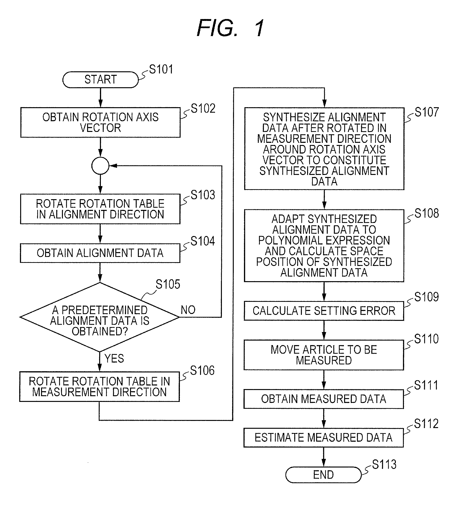
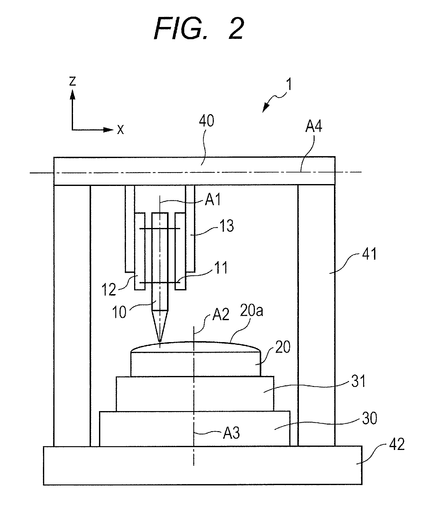
[0025]FIG. 1 is a flowchart of a contour shape measurement method according to Embodiment 1 of the present invention. FIG. 2 is a diagram of a probe-type shape measurement device according to Embodiment 1 of the present invention.

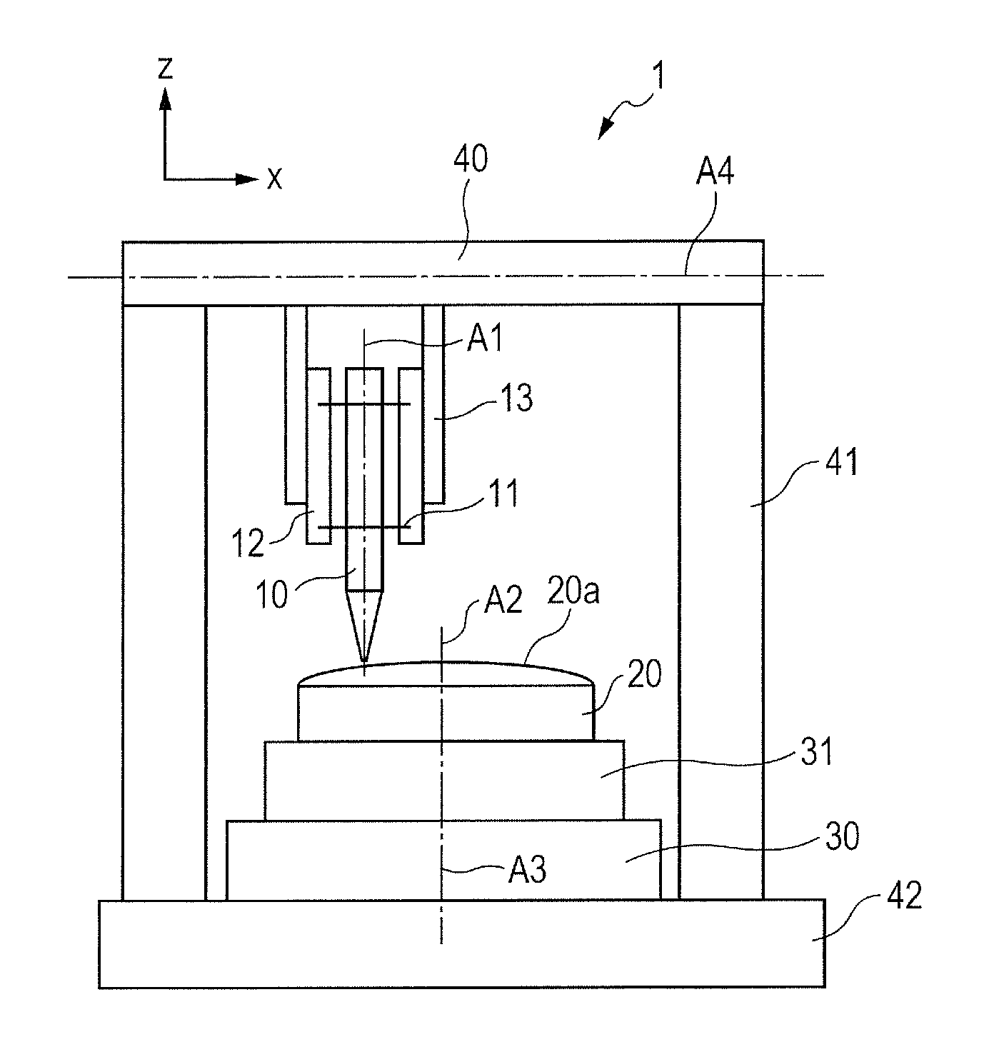
[0026]A structure of a probe-type shape measurement device 1 according to Embodiment 1 of the present invention is described first, with reference to FIG. 2.

[0027]A probe 10 used for scanning along a surface 20a to be measured of an article 20 to be measured is supported by a housing 12 via flat springs 11. Two flat springs 11 are attached in parallel. By being attached in this way, the flat springs 11 function as a linear guide for moving the probe 10 in a uniaxial direction with respect to the housing 12.

[0028]The flat springs 11 also function as a spring element for generating a force according to the relative position of the ...


PUM

PropertyMeasurementUnit
rotation tableaaaaaaaaaa
rotation angleaaaaaaaaaa
rotation axisaaaaaaaaaa

Abstract

A contour shape measurement method that can more accurately align an article to be measured to a predetermined position to enable high-precision evaluation even in a state where a probe measurement axis and a table rotation axis do not match with sufficient precision is provided. A spatial position of the table rotation axis relative to the probe measurement axis is obtained as a rotation axis vector. Alignment data obtained in at least two directions is coordinate-transformed around the rotation axis vector, to constitute synthesized alignment data. The article is aligned based on the synthesized alignment data. Since three-dimensional data of a surface to be measured of the article can be calculated, the article can be directly aligned to the probe measurement axis.

Description

BACKGROUND OF THE INVENTION[0001]1. Field of the Invention[0002]The present invention relates to a contour shape measurement method for precisely measuring a shape of an optical element or a mold for manufacturing an optical element.[0003]2. Description of the Related Art[0004]A probe-type shape measurement device is widely used to measure a shape of a surface to be measured of an article to be measured such as an optical element or a mold. An example of the probe-type shape measurement device is a shape measurement device disclosed in Japanese Patent Application No. H08-29153. This shape measurement device measures the shape of the surface, by performing a scan with a probe along the shape of the surface and simultaneously obtaining oscillation information of the probe in chronological order. A line scanned with the probe on the surface is referred to as “scan line”. With such a structure, the shape of the surface along the scan line is obtained as measured data.[0005]Typically, a ...

Claims


Application Information

Patent Timeline
Patent Type & Authority Patents(United States)
IPC IPC(8): G01B5/20G01B5/00G01M11/00G01B21/04
CPCG01B5/20G01B5/0021G01B21/04G01M11/30Y10T29/49764G01B5/245G01B5/25G01B5/252G01B21/20G01B21/24
Inventor MIYATA, AKINORI
Owner CANON KK
Why Eureka
Try Eureka