CPAP system with heat moisture exchange (HME) and multiple channel hose

a technology of heat moisture exchange and cpap, which is applied in the direction of breathing masks, breathing protection, other medical devices, etc., can solve the problems of individuals having difficulty breathing during sleep

Active Publication Date: 2015-10-13
HUMAN DESIGN MEDICAL
View PDF8 Cites 28 Cited by
  • Summary
  • Abstract
  • Description
  • Claims
  • Application Information

AI Technical Summary

Benefits of technology

[0005]It has been recognized that users generally prefer to breathe freely rather than fighting the pressurized air when possible. However, the user needs to have the mask on at certain times such as sleeping so that the system can provide pressurized air when required. The mask as described allows the user to both breathe freely when possible and switch modes when pressurized air is required.

Problems solved by technology

Certain individuals have difficulty breathing during sleep due to a collapse or obstruction of airways.

Method used


Image

  • CPAP system with heat moisture exchange (HME) and multiple channel hose
  • CPAP system with heat moisture exchange (HME) and multiple channel hose
  • CPAP system with heat moisture exchange (HME) and multiple channel hose

Examples


Embodiment Construction

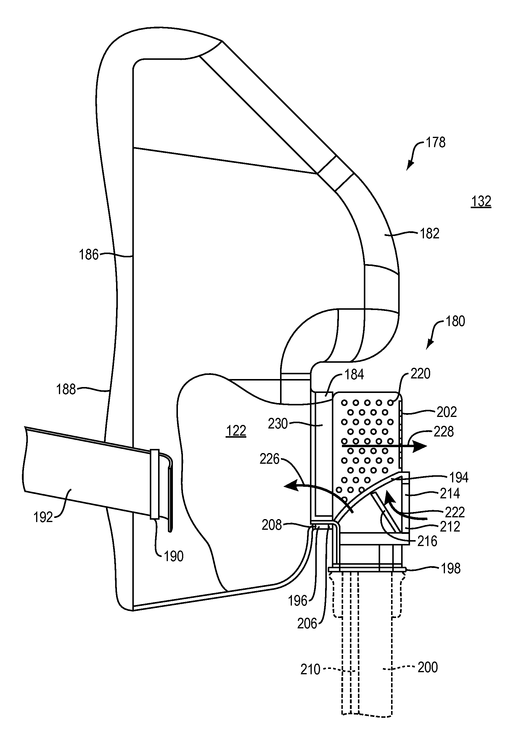
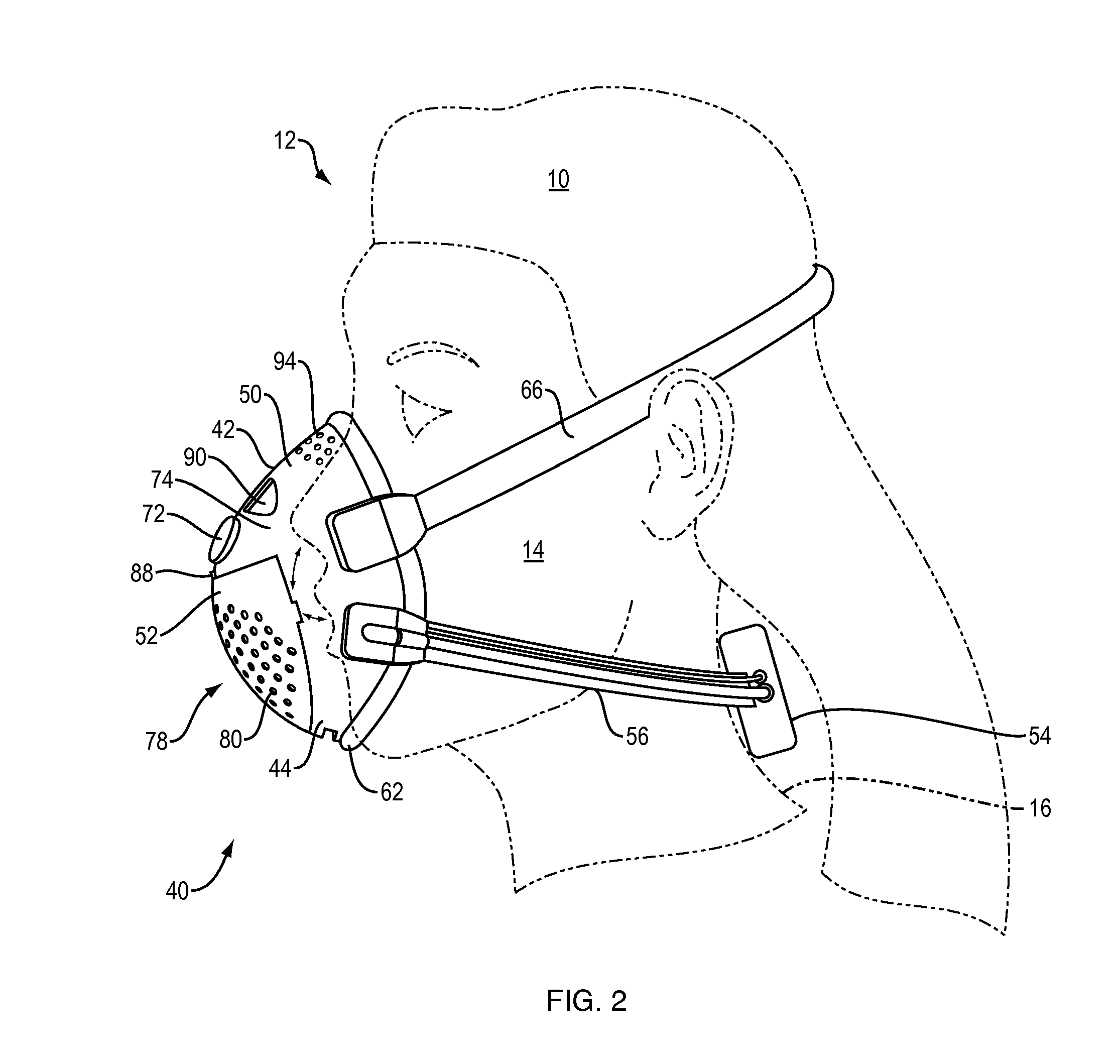
[0047]A continuous positive airway pressure (CPAP) system provides positive airway pressure therapy. The system described has a mask that is coupled to a user's face to deliver pressurized gas to an airway of the user. The system has a flow generator system that pressurizes gas. The flow generator system includes at least one motor. The system has a washout vent that allows fluid communication, separately from the flow generator system, between an interior of the mask and an exterior of the mask. The system has an unassisted breathing vent that allows fluid communication, separately from the flow generator system and the at least one washout vent, between an exterior of the mask and an interior of the mask. A check-valve carried by the mask obstructs the at least one unassisted breathing orifice during operation of the flow generator.

[0048]The abbreviation CPAP stands for continuous positive air pressure which in generic terms is a method of noninvasive or invasive ventilation assis...


PUM


Abstract

A continuous positive airway pressure (CPAP) system provides positive airway pressure therapy. It has been recognized that users generally prefer to breathe freely rather than to fight the pressurized air when possible. A continuous positive airway pressure (CPAP) system provides positive airway pressure therapy when required, but allows the user to breathe freely with the mask on when positive airway pressure is not required. The system has a valve that moves between two positions to open and close the unassisted breathing vent and the outlet from the flow generator.

Description

CROSS-REFERENCE TO RELATED APPLICATIONS[0001]This application is a continuation-in-part of U.S. patent application Ser. No. 13 / 452,823 filed on Apr. 20, 2012 which is a continuation-in-part of PCT Application PCT / US2010 / 053370 filed on Oct. 20, 2010 which claims the benefit of U.S. Patent Application 61 / 253,500 filed on Oct. 20, 2009, U.S. Patent Application 61 / 288,290 filed on Dec. 19, 2009, and U.S. Patent Application 61 / 301,151 filed on Feb. 3, 2010 and claims the benefit of U.S. Patent Application 61 / 560,271 filed on Nov. 15, 2011, which are incorporated herein by reference. In addition this application is a continuation-in-part of U.S. patent application Ser. No. 13 / 450,614 filed on Apr. 19, 2012 which is a continuation-in-part of PCT Application PCT / US2010 / 053370 filed on Oct. 20, 2010 which claims the benefit of U.S. Patent Application 61 / 253,500 filed on Oct. 20, 2009, U.S. Patent Application 61 / 288,290 filed on Dec. 19, 2009, and U.S. Patent Application 61 / 301,151 filed on ...

Claims


Application Information

Patent Timeline
Patent Type & Authority Patents(United States)
IPC IPC(8): A61M16/06A61M16/08A61M16/10A61M16/20A61M16/00
CPCA61M16/06A61M16/0069A61M16/0875A61M16/1095A61M16/204A61M2205/332A61M2230/432A61M16/1045A61M16/208A61M2016/0027A61M2016/0033A61M2016/1025A61M2205/18A61M16/0816A61M16/107
Inventor LALONDE, MICHAEL G.
Owner HUMAN DESIGN MEDICAL
Why Eureka
Try Eureka