Transmission cable installation device

a technology of transmission cable and installation device, which is applied in the direction of fibre mechanical structure, instruments, electrical equipment, etc., can solve the problems of reducing the effectiveness with which a cable can be passed along the duct, difficult to obtain, and not always possible, and achieves the effect of more rapid and convenient operation

Active Publication Date: 2015-10-13
FRANCE TELECOM SA
View PDF34 Cites 0 Cited by
  • Summary
  • Abstract
  • Description
  • Claims
  • Application Information

AI Technical Summary

Benefits of technology

[0020]The installation device of an embodiment of the invention improves and simplifies cabling the terminal portion by limiting failures and risks of damaging cables while they are being installed.
[0039]The protective sheath containing a rigid support in its recess enables installation to be performed more quickly and more easily in buildings.

Problems solved by technology

Reusing such cable ducts avoids laying additional cables where they are visible, where such a solution often requires the collective approval of a condominium, which is often difficult to obtain.
Nevertheless, this is not always possible, either because the existing cable duct does not have enough room, or because the building does not have any such cable ducts (as in old buildings, for example).
. . , but that reduces the effectiveness with which a cable can be passed along a duct.
Those force limits are such that an agent installing the cable and pulling it by hand can rapidly reach and exceed those limits, thereby damaging or even breaking the fiber under certain conditions of cable bending.
Pulling a cable along a duct that is readily occupied by other cables increases those risks.
It is not possible to envisage creating intermediate assistance points along a duct since that would require walls to be pierced, giving rise to delays and extra costs.
These precautions are not compatible with economic imperatives of passing a cable in a minimum amount of time.

Method used


Image

  • Transmission cable installation device
  • Transmission cable installation device
  • Transmission cable installation device

Examples


first embodiment

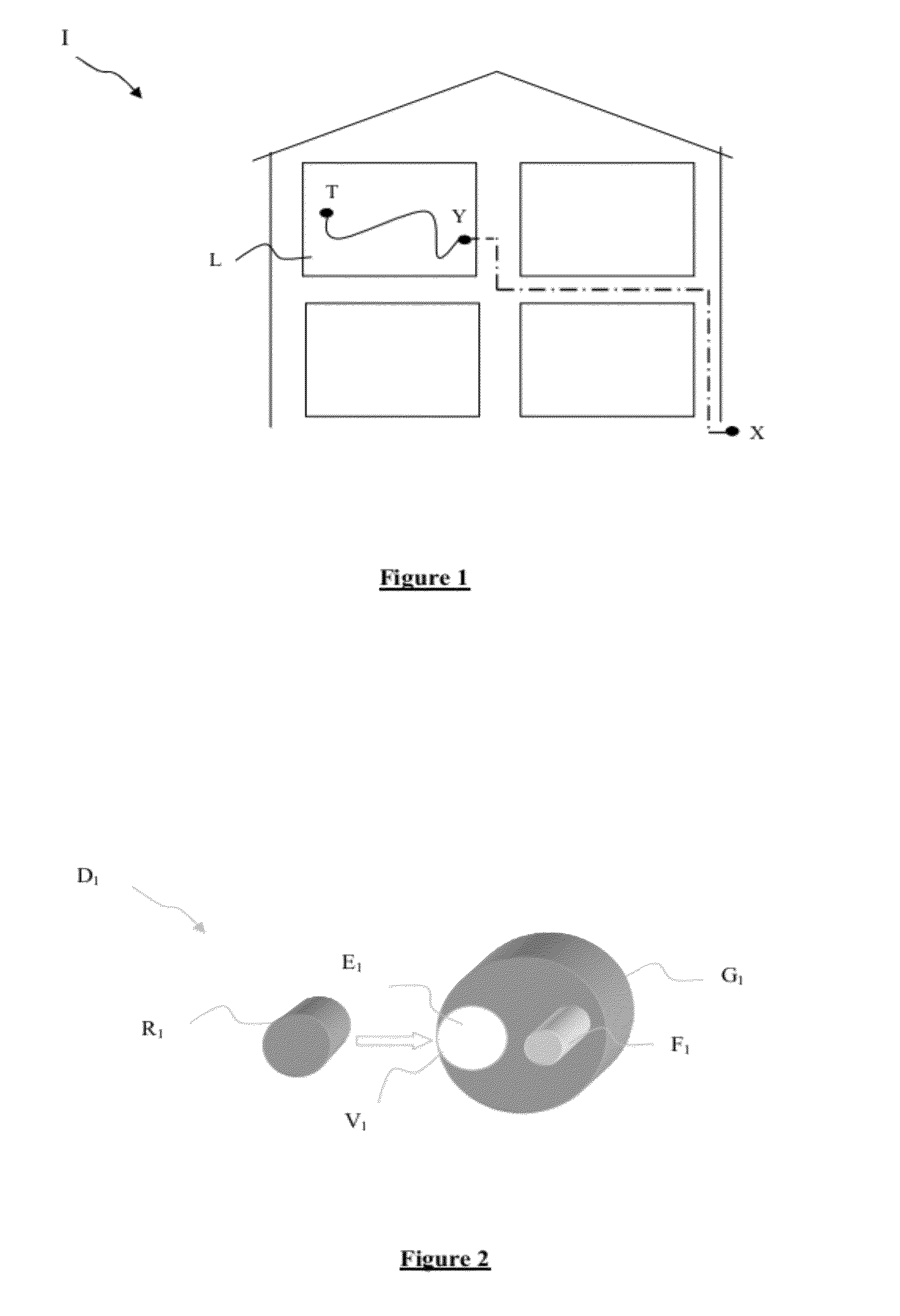
[0056]An installation device D1 constituting the invention is described below with reference to FIG. 2.

[0057]The installation device D1 comprises a protective sheath G1 and a rigid element R1.

[0058]The protective sheath G1 surrounds an optical cable F1 having one or more optical fibers.

[0059]As an alternative, the protective sheath G1 surrounds a plurality of optical cables.

[0060]The optical cable F1 may for example be a flexible optical cable with little sensitivity to radius of curvature. The characteristics of such a cable are described for example in ITU Recommendation G657 “Characteristics of a bending loss insensitive single mode optical fiber and cable for the access network”. By way of example, its diameter may be 0.25 mm. The optical cable F1 constitutes an example of a transmission cable in the meaning of an embodiment of the invention.

[0061]As an alternative, the diameter of the optical cable F1 may be greater than 0.25 mm.

[0062]The protective sheath G1 is fabricated arou...

second embodiment

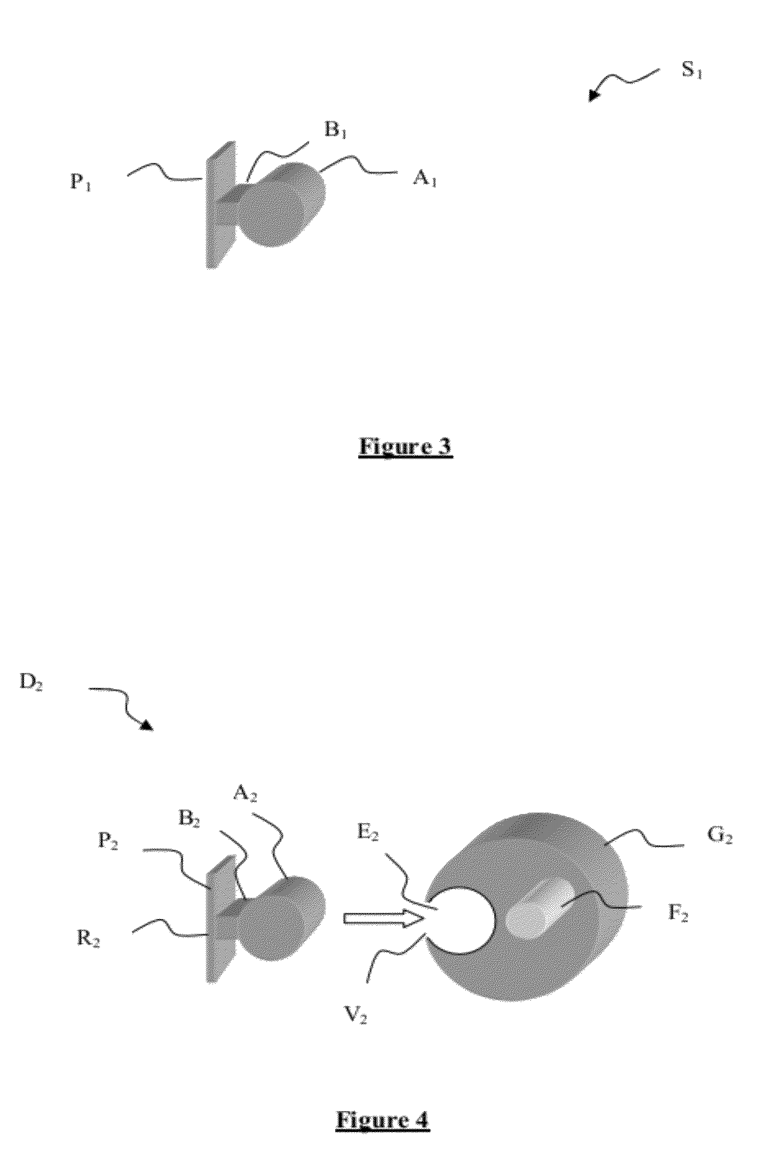
[0096]the installation device is described below with reference to FIG. 4.

[0097]The installation device D2 comprises a protective sheath G2 and a rigid element R2.

[0098]The protective sheath G2 surrounds an optical cable F2 containing one or more optical fibers.

[0099]A recess E2 is made in the protective sheath G2. The protective sheath G2 possesses a longitudinal slot V2 for removing or inserting the rigid element R2 from or into the sheath G2.

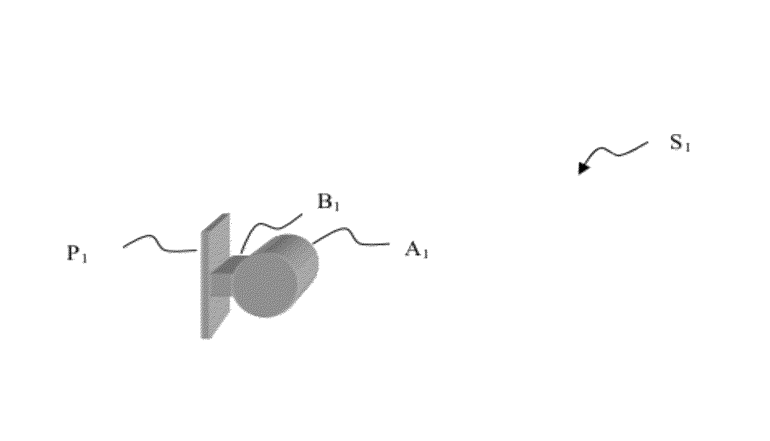
[0100]The rigid element R2 is a profiled support presenting a cylindrical portion A2, a constriction B2, and a baseplate P2.

[0101]The cylindrical portion A2 is suitable for being inserted in the recess E2. The constriction B2 serves to hold the profiled support R2 in the installation device D2 while it is being passed along a conduit. The baseplate P2 enables the profiled support to be fastened easily onto an apartment wall for supporting it.

[0102]During the fastening stage, the profiled support R2 is extracted from the protective sheath G2 o...

third embodiment

[0104]FIG. 5 shows an installation device D3 comprising a protective sheath G3 and a rigid element R3. The protective sheath D3 has a first recess E3 suitable for receiving the rigid element R3. It also has two other recesses E31 and E32 suitable respectively for receiving a first transmission cable, e.g. an optical cable, and a second transmission cable, e.g. a pair of copper wires for making a telephone connection of the public switched telephone network (PSTN) type.


PUM


Abstract

A transmission cable installation device is provided, which includes a protective sheath surrounding at least one transmission cable and having at least one longitudinal recess. A rigid element is inserted in one of said at least one recess. Also provided are a protective sheath and a profiled support suitable for being inserted in a recess in the protective sheath.

Description

CROSS-REFERENCE TO RELATED APPLICATIONS[0001]This Application is a Section 371 National Stage Application of International Application No. PCT / FR2010 / 052059, filed Sep. 30, 2010, which is incorporated by reference in its entirety and published as WO 2011 / 039479 on Apr. 7, 2011, not in English.STATEMENT REGARDING FEDERALLY SPONSORED RESEARCH OR DEVELOPMENT[0002]None.THE NAMES OF PARTIES TO A JOINT RESEARCH AGREEMENT[0003]None.FIELD OF THE DISCLOSURE[0004]The present disclosure relates to the field of laying cables in buildings.BACKGROUND OF THE DISCLOSURE[0005]In order to cable terminal portions in buildings, such as apartment blocks or offices or houses, and in order to serve such buildings with additional cables such as optical fiber cables, telephone cables, electric cables, and TV cables, telecommunications network operators make use, wherever possible, of existing tubular infrastructure, comprising various cable ducts already present in buildings.[0006]Such cable ducts are prese...

Claims


Application Information

Patent Timeline
Patent Type & Authority Patents(United States)
IPC IPC(8): H02G1/08H02G3/04G02B6/44
CPCH02G3/0481G02B6/4429G02B6/4495G02B6/4471H02G1/08G02B6/4431
Inventor CAMPION, JEAN-LUCLOUBOUTIN, JEAN-PIERRELANDOUAR, JEAN-MICHEL
Owner FRANCE TELECOM SA
Why Eureka
Try Eureka